Stent with increased longitudinal flexibility and scaffolding

a stent and longitudinal flexibility technology, applied in the field of stents, can solve the problems of stent longitudinal rigidity, and high morbidity and mortality, and achieve the effects of adequate radial strength, adequate radial strength, and adequate scaffolding

Active Publication Date: 2005-04-21
MEDTRONIC VASCULAR INC
View PDF11 Cites 18 Cited by
  • Summary
  • Abstract
  • Description
  • Claims
  • Application Information

AI Technical Summary

Benefits of technology

[0020] The stent of the present invention is thereby flexible because, for example, the longitudinal links are intermittently spaced in a staggered configuration along the stent's longitudinal axis. Additionally, the stent of the present invention provides adequate support to a vessel wall because, for example, the circumferential gaps created by the intermittent use of longitudinal links have been substantially filled in with inter

Problems solved by technology

One of the major complications associated with using stents has been thrombosis.
The complication is caused by clotting in the vicinity of the stent and is associated with high morbidity and mortality.
This complication is caused by build up of plaque on the vessel's inner wall after the stent is in place.
However, such conventional stents suffer from predilation stent longitudinal rigidity.
Accordingly, predilation longitudinal stent rigidity makes it much harder and oftentimes even impossible to thread the stent through long tortuous vessels and past constric

Method used


Image

  • Stent with increased longitudinal flexibility and scaffolding
  • Stent with increased longitudinal flexibility and scaffolding
  • Stent with increased longitudinal flexibility and scaffolding

Examples


Embodiment Construction

[0025] The foregoing and other features and advantages of the invention will be apparent from the following, more detailed description of the preferred embodiment of the invention, as illustrated with reference to FIGS. 1-4. While specific embodiments are discussed in detail, it should be understood that this is done for illustrative purposes only. A person skilled in the art will recognize that other embodiments can be used without departing from the spirit and scope of the invention.

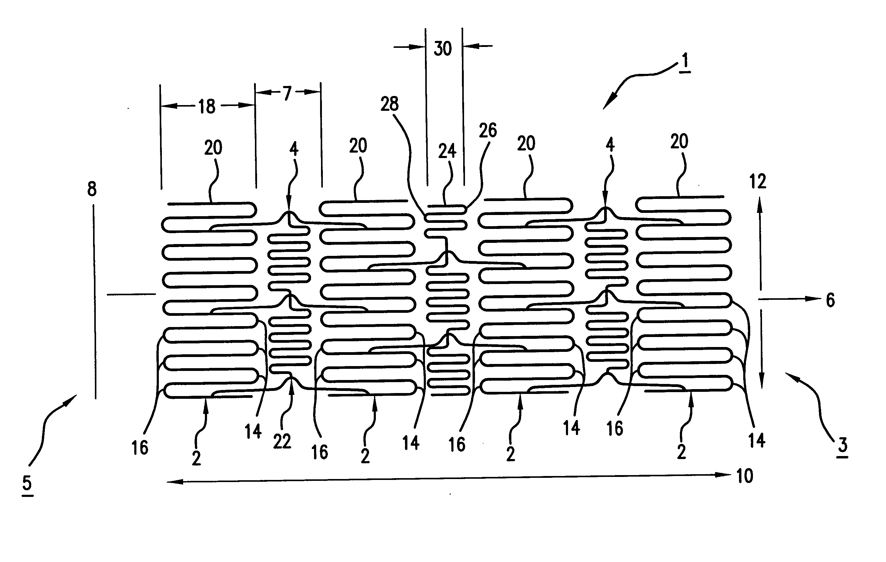
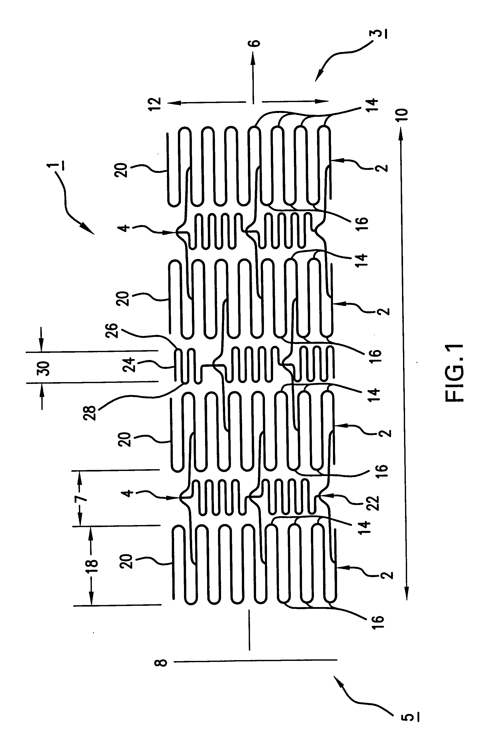
[0026]FIG. 1 shows a top view of a stent 1, which has been cut and laid open for illustrative purposes. In its unaltered state, stent 1 is generally hollow and cylindrical in shape (not shown). Stent 1 has a proximal end 3 and a distal end 5. Additionally, stent 1 has a longitudinal axis 6 and a transverse axis 12. Further, stent 1 has a horizontal length 10 measured along longitudinal axis 6 from proximal end 3 to distal end 5, and a circumference 8 measured around the stent circumference.

[0027] Ste...


PUM


Abstract

The present invention relates to a stent manufactured from a thin-walled tube of surgical implant quality. The stent comprises a plurality of main circumferential rings, a plurality of longitudinal links and a plurality of intermediate circumferential rings. The main circumferential rings are longitudinally spaced apart along a longitudinal axis. Circumferential gaps are formed between adjacent main circumferential rings. The longitudinal links span the gaps and are attached to adjacent main circumferential rings. The intermediate circumferential rings fill in the circumferential gaps and are attached to the longitudinal links. The present invention thereby provides a stent with adequate radial strength to properly deploy, adequate scaffolding affect to properly support vessel walls and increased longitudinal flexibility to easily maneuver through tortuous vessels.

Description

BACKGROUND OF THE INVENTION [0001] 1. Field of the Invention [0002] This invention relates generally to a novel stent design. More specifically, this invention relates to a stent having increased longitudinal flexibility with improved scaffolding affect. [0003] 2. Related Art [0004] A stent is a prosthesis that is inserted into a body lumen and used, for example, for treating stenoses, strictures, and / or aneurysms therein. In the event of a stenosed vessel, the stent is expanded to widen and sometimes completely reopen a lumen. Once opened, the stent forms to the inner wall of the vessel, remains in place, and acts as a deterrent to restenosis. Additionally, in the event of an aneurysm or weakened vessel wall, stents are useful for providing support to and reinforcing the vessel wall. [0005] To perform such functions, stents in the past have included many different structures. For example, previously disclosed stents include coiled stainless steel springs, helical wound springs, and...

Claims


Application Information

Patent Timeline
IPC IPC(8): A61F2/06A61F2/90
CPCA61F2/91A61F2/915A61F2002/91583A61F2002/91525A61F2002/91533A61F2002/91516
Inventor THORNTON, RONAN
Owner MEDTRONIC VASCULAR INC
Why Eureka
Try Eureka