Signal configuration based transmitter adjustment in wireless communication devices

Active Publication Date: 2006-03-30
GOOGLE TECH HLDG LLC
View PDF13 Cites 68 Cited by
  • Summary
  • Abstract
  • Description
  • Claims
  • Application Information

AI Technical Summary

Problems solved by technology

As data rates increase in wireless communication networks & handsets, the power amplifier (PA) headroom demands placed on transmitters tends to increase, which decreases overall transmitter efficiency.
The PA consumes the largest portion of battery p

Method used


Image

  • Signal configuration based transmitter adjustment in wireless communication devices
  • Signal configuration based transmitter adjustment in wireless communication devices
  • Signal configuration based transmitter adjustment in wireless communication devices

Examples


Embodiment Construction

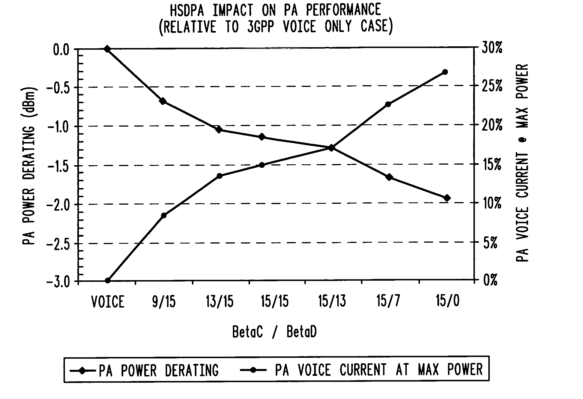
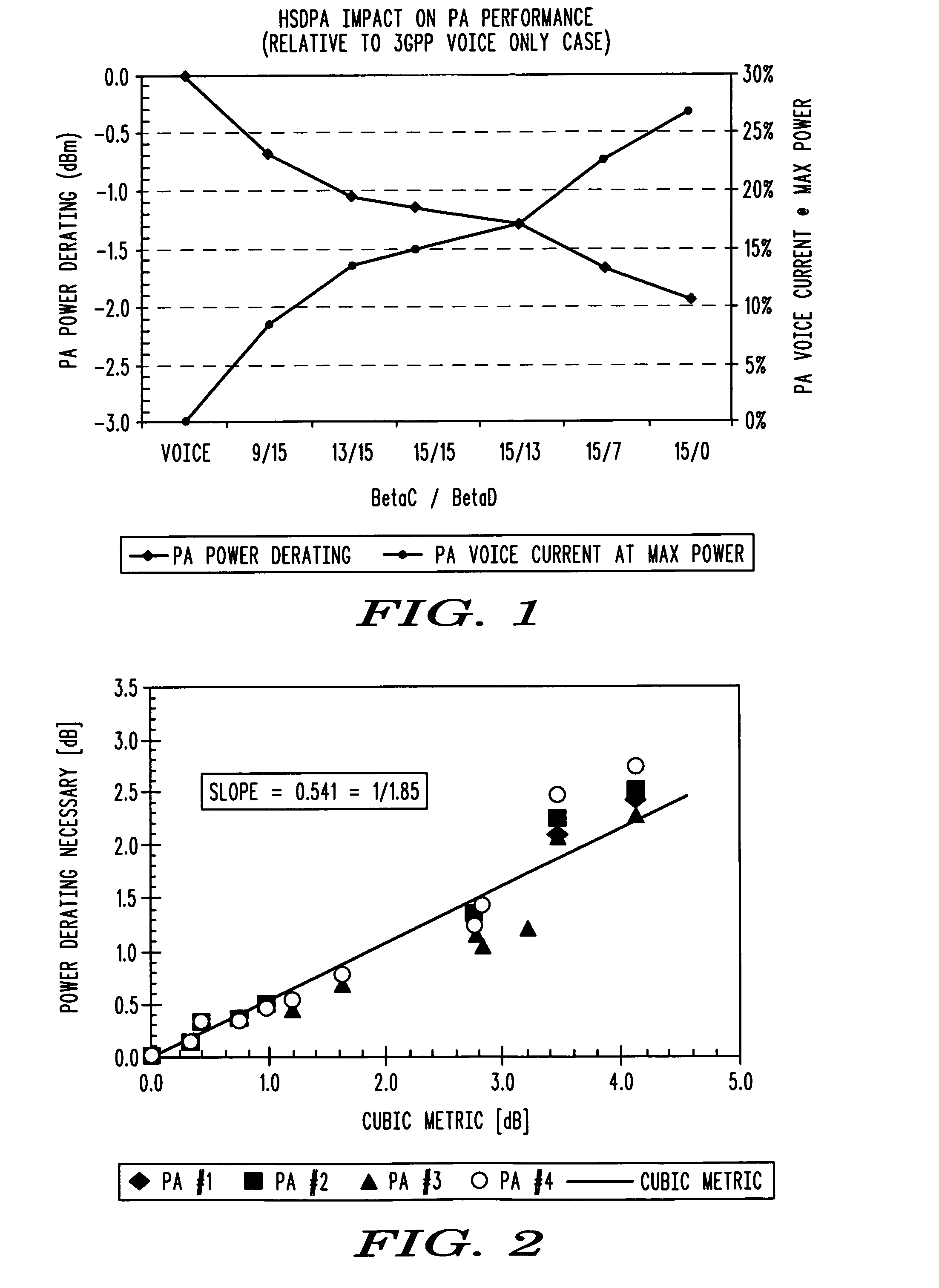
[0013]FIG. 1 illustrates PA linear power capability de-rating as a function of control / data channel gain ratios. Generally, the maximum power at which Adjacent Channel Leakage Ratio (ACLR) and error vector magnitude (EVM) level limits can be met for a power amplifier (PA) varies with the channel or signal configuration. FIG. 1 also illustrates that the linear power capability of a PA can be degraded by as much as 2 dB over the full range of 3GPP Release 5 High Speed Downlink Packet Access (HSDPA) channel configurations.

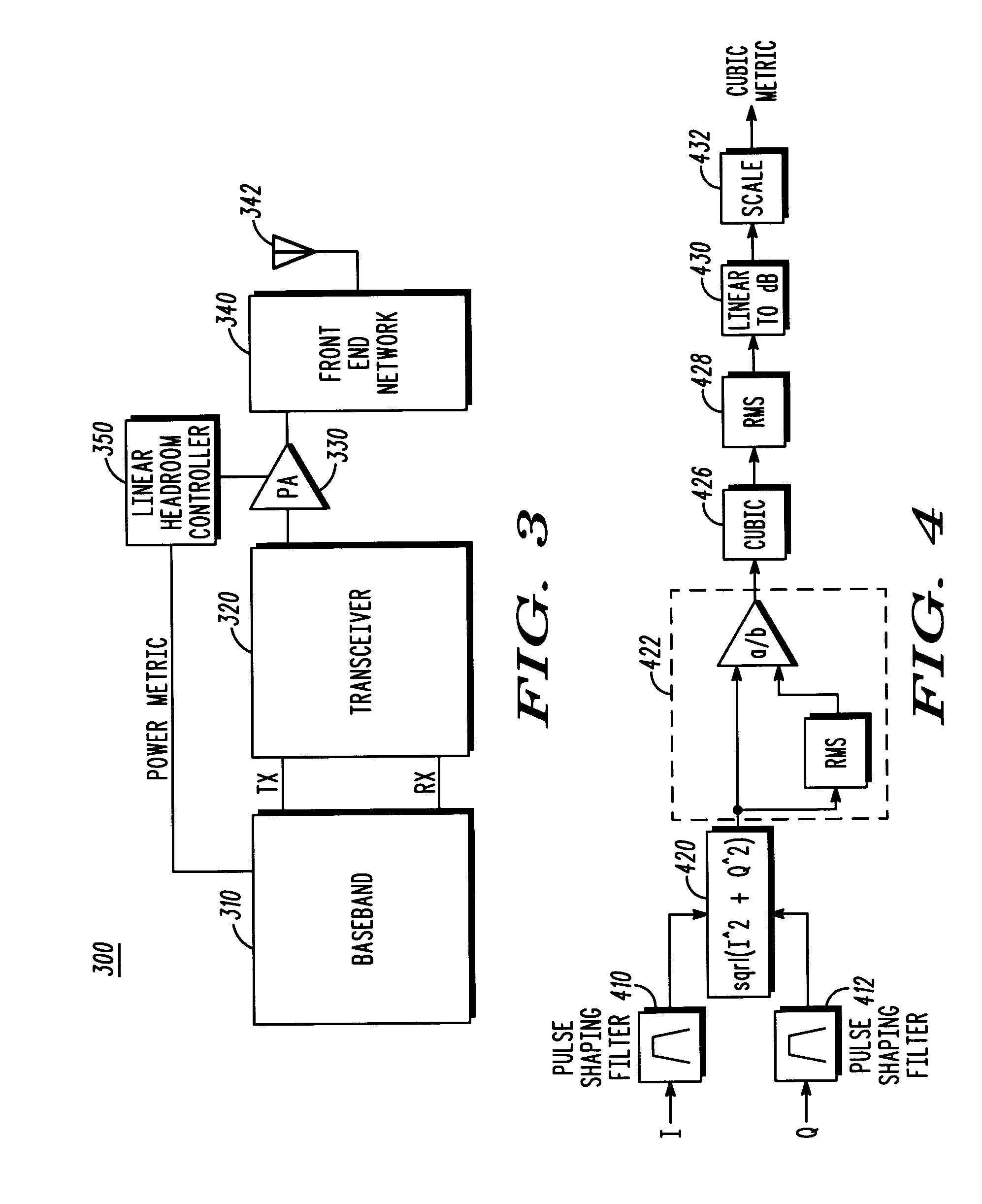
[0014] First generation 3GPP WCDMA power amplifiers (PAs) were designed to provide linear amplification for a basic signal configuration including one control channel and one data channel with a known peak-to-average ratio (PAR) of approximately 3 dB. With this configuration, maximum power and efficiency could be optimized simultaneously while maintaining acceptable Adjacent Channel Leakage Ratio (ACLR) and error vector magnitude (EVM) levels. Future wireless communi...


PUM


Abstract

A method in a wireless communication transmitter including a baseband processor (310) that dynamically configures the transmitter for a particular signal configuration, and a headroom controller (350) for adjusting transmitter headroom based on the particular signal configuration. In one embodiment, the PA headroom is controlled based on a power metric, for example, a 3rd order polynomial or peak to average ratio (PAR) metric, that is a function of the signal configuration. In another embodiment the PA headroom is adjusted using information in a look up table.

Description

FIELD OF THE DISCLOSURE [0001] The present disclosure relates generally to wireless communication transmitters, and more particularly to adjusting transmitter power amplifiers based on transmitter signal configuration, for example, the channel configuration in high speed uplink and downlink data access enabled wireless communication devices, and methods. BACKGROUND OF THE DISCLOSURE [0002] As data rates increase in wireless communication networks & handsets, the power amplifier (PA) headroom demands placed on transmitters tends to increase, which decreases overall transmitter efficiency. The effect is a reduction in talk or packet connect times and an increase in operating temperature. The PA headroom is a measure of the power margin available for producing higher levels of RMS output power for a given reference signal or transmitter configuration, and / or for amplifying signals having a higher peak-to-average power ratio (PAR) at a maximum rated RMS power level. [0003] The PA consum...

Claims


Application Information

Patent Timeline
IPC IPC(8): H04Q7/20H04W52/36
CPCH03F1/0211H03F1/0244H03F1/0261H04W52/367H04B2201/70706H04B2201/70707H04B2001/0416H03F1/02H04B1/04
Inventor KLOMSDORF, ARMIN W.LOVE, ROBERT T.SCHIRMANN, ERNESTSCHWENT, DALE G.
Owner GOOGLE TECH HLDG LLC
Why Eureka
Try Eureka