Wireless Communication System, Wireless Communication Device and Wireless Communication Method, and Computer Program

a wireless communication and wireless communication technology, applied in the field of wireless communication systems, wireless communication devices and wireless communication methods, and computer programs, can solve the problems of ad hoc mode, reduced throughput, and reduced utilization efficiency of transfer paths, and achieve the effect of reducing power consumption

Active Publication Date: 2008-08-07
SONY CORP
View PDF15 Cites 215 Cited by
  • Summary
  • Abstract
  • Description
  • Claims
  • Application Information

AI Technical Summary

Benefits of technology

[0015]With an infrastructure mode which routes via the control station, the various terminal stations thereunder can be connected to a backbone network such as a cable LAN or the Internet. However, since wireless communication via a control station is necessary, the usage efficiency of a transfer path is decreased by half, causing a problem wherein throughput is decreased as compared to the ad hoc mode. On the other hand with the ad hoc mode, there is no overhead from the control station relay since the terminal stations directly communicate with one another and thus throughput increases, but there is the problem of not being able to connect to a backbone network such as a cable LAN or the Internet.

Problems solved by technology

However, since wireless communication via a control station is necessary, the usage efficiency of a transfer path is decreased by half, causing a problem wherein throughput is decreased as compared to the ad hoc mode.
On the other hand with the ad hoc mode, there is no overhead from the control station relay since the terminal stations directly communicate with one another and thus throughput increases, but there is the problem of not being able to connect to a backbone network such as a cable LAN or the Internet.
However, even if DLP is performed to establish direct communication, if the communication partner is not in a location where sufficient waves can reach, and a location where communication quality can be obtained, i.e. if the communication partner is not within the direct link range, this can result in decreased throughput due to frequent packet errors and the like.

Method used


Image

  • Wireless Communication System, Wireless Communication Device and Wireless Communication Method, and Computer Program
  • Wireless Communication System, Wireless Communication Device and Wireless Communication Method, and Computer Program
  • Wireless Communication System, Wireless Communication Device and Wireless Communication Method, and Computer Program

Examples


first embodiment

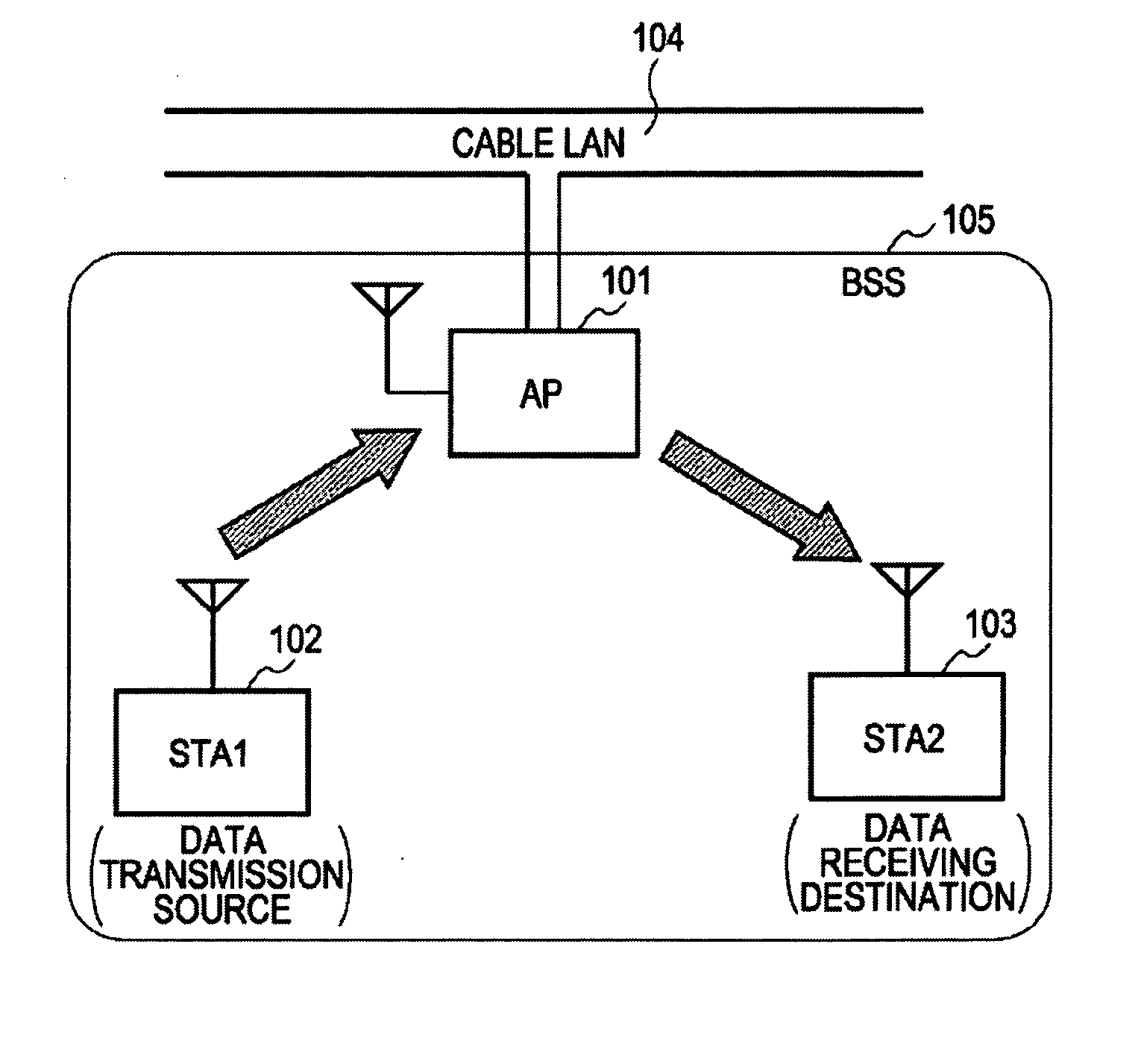
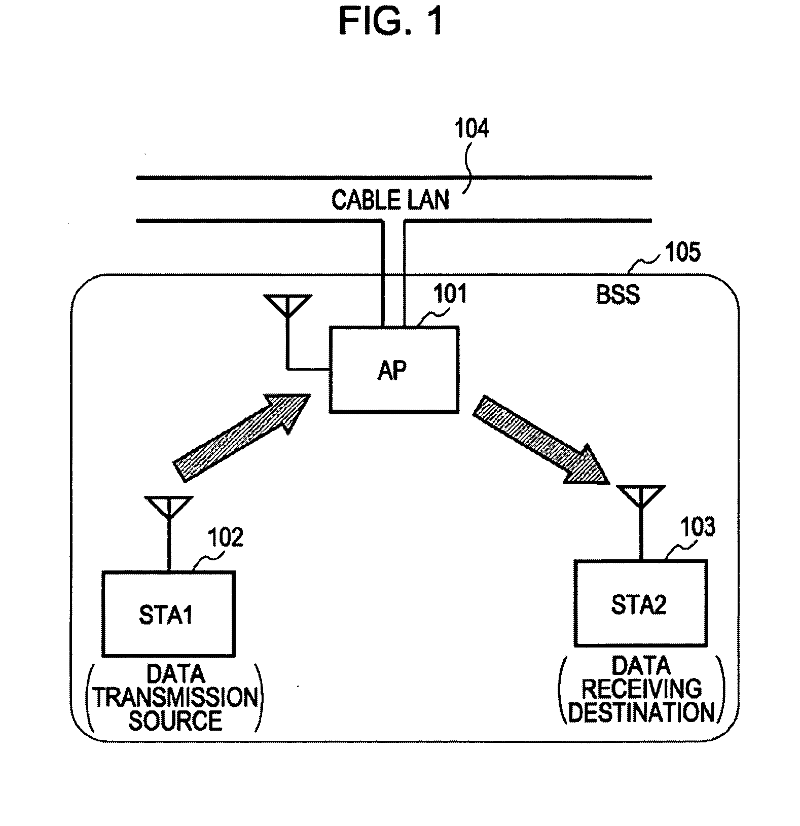
[0111]With the first embodiment, the first terminal station 102 serving as the data transmission source starts establishing a direct link according to the procedures shown in FIG. 3. Hereafter, in the embodiments, each process will be described from “start trigger”, “detect direct link”, “evaluate direct link”, “link establishing request”, and “response to link establishing request” up to establishing a link.

Start Trigger

[0112]The first terminal station 102 serving as the data transmission source uses the transmitting of the data (of the generating of a data transmission request at the upper layer) itself as a trigger for a direct link test. Also, in the case that the first terminal station 102 serving as a content server system or the like, the receiving of a packet for content obtaining request from the second terminal station 103 serving as the client may be used as a trigger for a direct link test. In the case that the trigger condition is satisfied, the data processing unit 201...

second embodiment

[0162]With the second embodiment also, the first terminal station 102 serving as the data transmission source starts establishing a direct link according to the procedures shown in FIG. 3, as a main unit. The starting trigger thereof is similar to that in the first embodiment. However, the second embodiment differs from the first embodiment in that the direct link detecting processing and direct link evaluating processing are simultaneously executed.

[0163]FIGS. 10A and 10B show the processing procedures for simultaneously executing direct link detecting processing and direct link evaluating processing according to the second embodiment.

[0164]The first terminal station 102 sends a Direct Test Request packet for requesting the start of the direct link evaluating processing to the second terminal station 103 via the control station 101 (S1002). The Direct Link Test Request is encapsulated in the data-type frame, and can be sent in the same format as the managing frame of IEEE 802.11 (s...

third embodiment

[0175]With the third embodiment also, the first terminal station 102 serving as the data transmission source starts establishing a direct link according to the procedures shown in FIG. 3, as a main unit. The starting trigger thereof and the direct link detecting processing are similar to that in the first embodiment. However, the third embodiment differs from the first embodiment in that the direct link establishing processing and direct link evaluating processing are simultaneously executed.

[0176]FIGS. 11A and 11B show the processing procedures for simultaneously executing direct link evaluating processing and direct link establishing processing.

[0177]The first terminal station 102 sends a Direct Link Test & Establishment Request packet addressed to the second terminal station by relay of the control station 101 (S1102). The control station 101 transfers the Direct Link Test & Establishment Request packet when the second terminal station 103 is in the Awake state (step S1103).

[0178...


PUM


Abstract

A wireless communication system, wherein packet transmission operations are carried out in an infrastructure mode, includes: a first terminal station serving as a data transmission source; a second terminal station serving as a data receiving destination; and a control station configured to contain each terminal station and relay a packet transmitted between the two terminal stations; wherein the first terminal station transmits a packet addressed to the second terminal station via the control station, and detects that the second terminal station is within range capable of a direct link, based on the first terminal station receiving a confirmation response packet replied from the second terminal station, the confirmation response packet being replied from the second terminal station upon a predetermined period of time having passed from the time of the control station transferring the packet to the second terminal station address.

Description

CROSS REFERENCES TO RELATED APPLICATIONS[0001]The present invention contains subject matter related to Japanese Patent Application JP 2007-024136 filed in the Japanese Patent Office on Feb. 2, 2007, the entire contents of which are incorporated herein by reference.BACKGROUND OF THE INVENTION[0002]1. Field of the Invention[0003]The present invention relates to a wireless communication system, wireless communication device and wireless communication method, and computer program such as a wireless LAN (Local Area Network) wherein communication is performed mutually between multiple wireless stations, and in particular relates to a wireless communication system, wireless communication device and wireless communication method, and computer program wherein a control station adjusts access timing for various terminal stations within a network, and wherein various terminal stations are mutually synchronized to perform wireless communication in an infrastructure mode.[0004]2. Description of ...

Claims


Application Information

Patent Timeline
Patent Type & Authority Applications(United States)
IPC IPC(8): H04B7/14H04W8/00H04W56/00H04W74/04H04W76/02H04W84/12H04W88/04H04W92/18
CPCH04W8/005H04W92/18H04W88/04
Inventor ITAGAKI, TAKESHIITOH, KATSUTOSHI
Owner SONY CORP
Why Eureka
Try Eureka