
Removable duct liner

a duct liner and duct technology, applied in the field of air handling systems, can solve the problems of condensation on the surface of the duct, dust trapped, and inability to meet the needs of space,

Inactive Publication Date: 2006-04-06
WL GORE & ASSOC INC
View PDF5 Cites 16 Cited by
  • Summary
  • Abstract
  • Description
  • Claims
  • Application Information

AI Technical Summary

Problems solved by technology

Such metal or plastic ductwork air handling systems are problematic, however, because the registers can create drafts, air turbulence, resulting in undesirable temperature variations within the space.
Moreover, when the air source delivers air at a lower temperature than the space in which the duct is located, condensation may form on the surface of the duct.
As the air flows through the fabric, some dust will be trapped.
Consequently, such systems may offer limited secondary filtration, which may improve air quality in the space.
However, this also necessitates frequent cleaning to maintain air permeability.
High-throw devices enjoy most of the benefits of fabric air ducts, however because traditional fabrics may require additional processes to reduce permeability, these fabrics may be more expensive.
Unfortunately, fabric ducts require relatively frequent cleaning and the task of removing, washing, and reinstalling the fabric is complicated and expensive.
During removal and reinstallation, the duct may be damaged and there is a high probability of error in the reinstallation process.
Consequently, the filter performance is poor, and the filter will require relatively frequent replacement.

Method used


Image

  • Removable duct liner
  • Removable duct liner
  • Removable duct liner

Examples


example 1

[0055] A removable liner for a fabric duct was constructed as follows:

[0056] A porous expanded polytetrafluoroethylene film having an air permeability of about 40 F was used as the membrane layer. The membrane is available from W.L. Gore and Associates, Inc., Newark, Del. For support, a polyethylene / polyester spun bond bicomponent nonwoven having a basis weight of 0.45 oz / yd2 (15 g / m2) was used. The material is available from Marubeni America Corp. under the trade name MARIX®.

[0057] A sample of material was tested to determine its filtration efficiency and air permeability. The liner performance is contrasted with the performance of known commercially available porous duct materials availble from Ductsox® Fabric Air Dispersion Products, Dubuque, Iowa. The results are reported in Table 1. It is clear from the data that the duct liners of the present invention show improved filtration performance without sacrificing air permeability. Thus the liner will not signifcantly alter the pr...

example 2

[0058] An 18 F polytetrafluoroethylene filter membrane was laminated to a 15 g / m2 polyetheylene / polyester bicomponent spun bond.

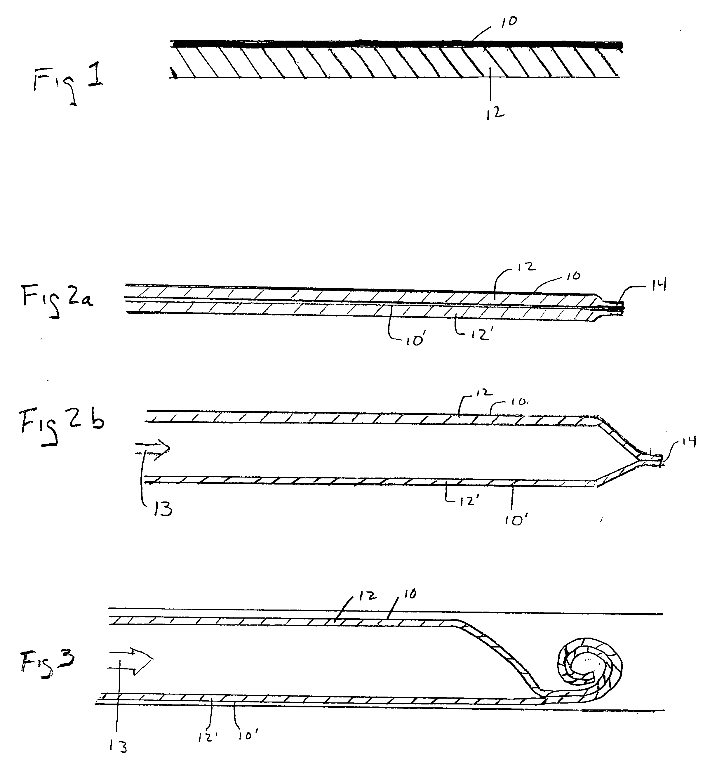
[0059] Two sheets measuring 414″ (10,515 mm) long and 18″ wide were cut from each of the membrane and the support materials. The sheets were superimposed upon each other such the two sheets of support material were positioned between two sheets of membrane material. Both longitudinal edges were heat welded using a hand iron such that all the sheets were joined at the edges. The edges were welded with a 1⅝″ (41 mm) wide weld using a hand iron manufactured by Heat Seal, Inc., Cleveland Ohio. The sealing was performed with the iron adjusted to the high temperature setting. The welder was run along the inside of two reference lines that were spaced 18″ apart. The welding formed a flattened tube approximately 18″ wide. One end of the tube was also heat welded to form the porous duct liner.

[0060] The porous duct liner was folded and rolled up to prepare it for ...


PUM


Abstract

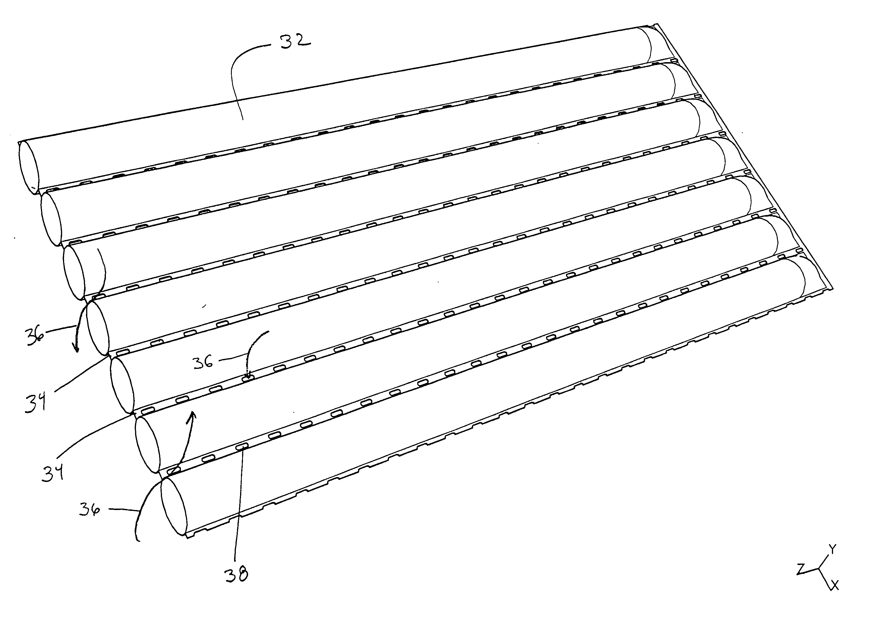
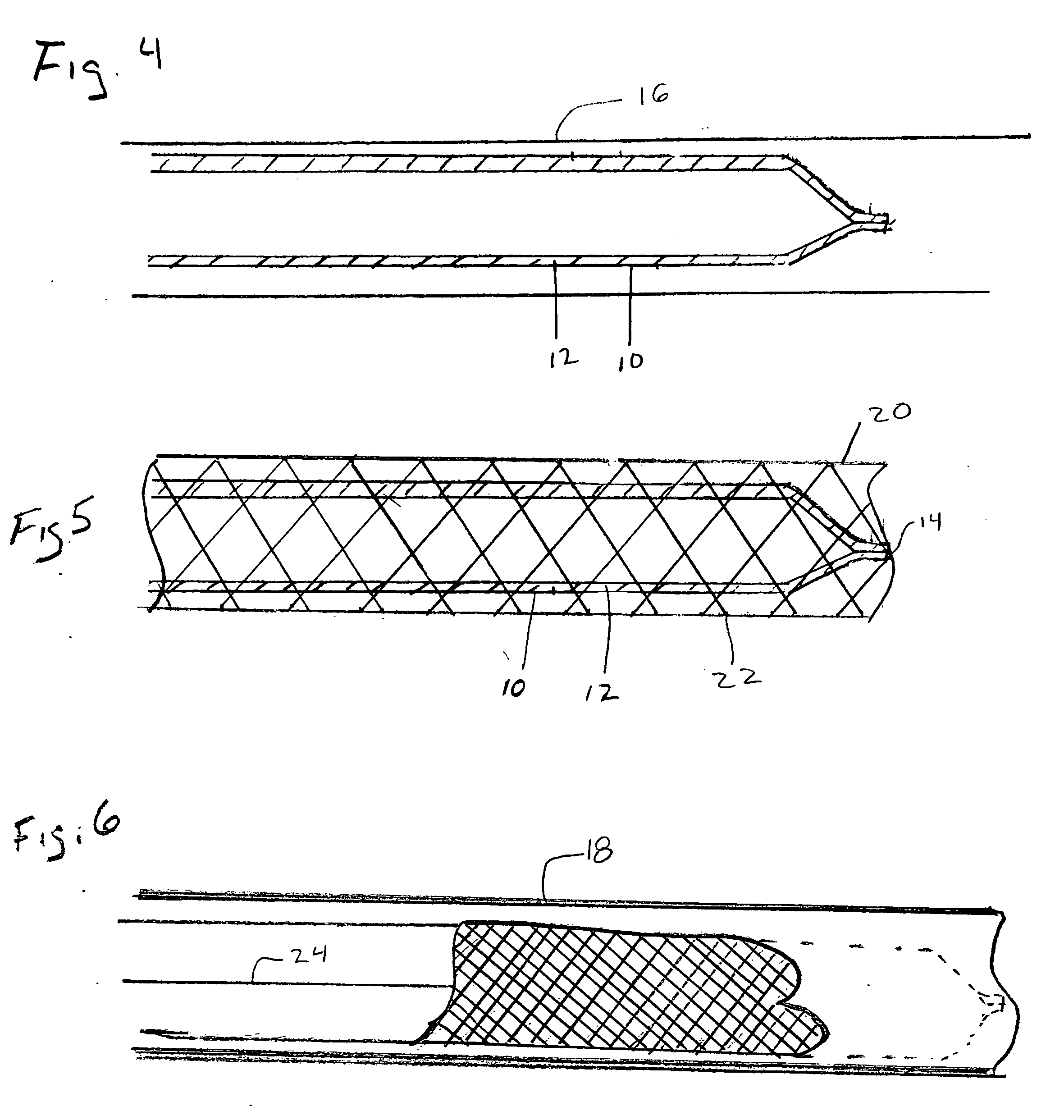
The invention relates to liners for air ducts. Specifically, the invention is an article comprising a porous polymeric membrane layer and, optionally, a support layer, in which the article is a duct liner adapted to be removably positioned within a porous air duct. The liner may also be used in conventional metal and plastic ducts to reduce cleaning frequency. In another aspect, the invention is a porous air duct comprising: a liner comprising a porous polymeric membrane and, optionally, a support layer; and an openwork conduit, said liner disposed within the openwork conduit.

Description

BACKGROUND OF THE INVENTION [0001] A variety of air handling systems are known in the art for conveying and distributing air from a source of forced air (i.e., a heater, an air-conditioner, a humidifier, a de-humidifier, or any other device which supplies pressurized air) to a room, building, or other enclosure (collectively, a “space”). [0002] One common air handling system utilizes metal or plastic ductwork connected to a forced air source and has spaced registers for discharging air therefrom into the space. Such metal or plastic ductwork air handling systems are problematic, however, because the registers can create drafts, air turbulence, resulting in undesirable temperature variations within the space. Moreover, when the air source delivers air at a lower temperature than the space in which the duct is located, condensation may form on the surface of the duct. [0003] Duct systems using fabric tubes supported by framing systems rather than impermeable metal or plastic structure...

Claims


Application Information

Patent Timeline
IPC IPC(8): B01D53/22
CPCF24F13/0218
Inventor STARK, STEPHEN K.SASSA, ROBERT L.
Owner WL GORE & ASSOC INC
Learn More