Advanced "Omer" rescue system

a rescue system and advanced technology, applied in the field of advanced " omer " rescue systems, can solve the problems of insufficient emergency response of devices, inconvenient escape methods of these devices, and insufficient device use for escapees

Inactive Publication Date: 2006-04-06
BARZILAI YOAV
View PDF5 Cites 19 Cited by
  • Summary
  • Abstract
  • Description
  • Claims
  • Application Information

AI Technical Summary

Benefits of technology

[0016] According to the teachings of the present invention there is also provided, an anchoring system for anchoring a cord to a frame of a door or a window of a building, the frame including a plurality of elongated frame elements, the cord having a load thereon, the anchoring system comprising: (a) an elongated element having a first end and a second end, the elongated element being extendable; and (b) two gripping members, one of the gripping members being mechanically connected to the first end, another of the gripping members being mechanically connected to the second end, wherein the elongated element has an extension mechanism for applying an extension force to the elongated element so as to force the gripping members substantially against the frame, the gripping members being configured, such that, the gripping members substantially grip the frame thereby preventing the anchoring system from being pulled out of the frame by the load on the cord.
[0027] According to the teachings of the present invention there is also provided, a glider device for simultaneously controlling the descent of a person on a first cord and a second cord, the device comprising: (a) a housing having an internal volume, an inlet opening and an outlet opening, wherein: (i) the housing is configured such that, in operation the first cord passes through the inlet opening, the internal volume and the outlet opening; and (ii) the internal volume has a friction arrangement configured for applying a braking force to the first cord; (b) a control lever mechanically connected to the housing, such that the control lever moves within the housing, wherein the control lever and the housing are configured, such that: (i) when the control lever is held in a first position, the first cord passes moves relative to the housing thereby allowing descent of the person; and (ii) when the position of the control lever is uncontrolled, the first cord moves the control lever to a second position thereby applying a braking force to the first cord; and (c) a fail-safe arrangement mechanically connected to the housing, the fail-safe arrangement being configured for controlling relative movement of the second cord and the fail-safe arrangement, such that, when the second cord moves in relation to the fail-safe arrangement greater than a minimum speed, the fail-safe arrangement at least slows relative movement of the second cord and the fail-safe device.

Problems solved by technology

This is because the combined friction between the wider cord and the frictional surfaces of the glider device prevent effective movement of the cord.
Nevertheless, these devices do not sufficiently address situations where, an injured escapee cannot operate these devices by himself, or where, due to time constraints, there is a need to evacuate more than one person at the same time.
Additionally, the escape method of these devices may not be suitable or comfortable for many escapees.

Method used


Image

  • Advanced "Omer" rescue system
  • Advanced "Omer" rescue system
  • Advanced "Omer" rescue system

Examples


Embodiment Construction

[0062] The present invention is a rescue system construction and method of operation thereof.

[0063] The principles and operation of a rescue system according to the present invention may be better understood with reference to the drawings and the accompanying description.

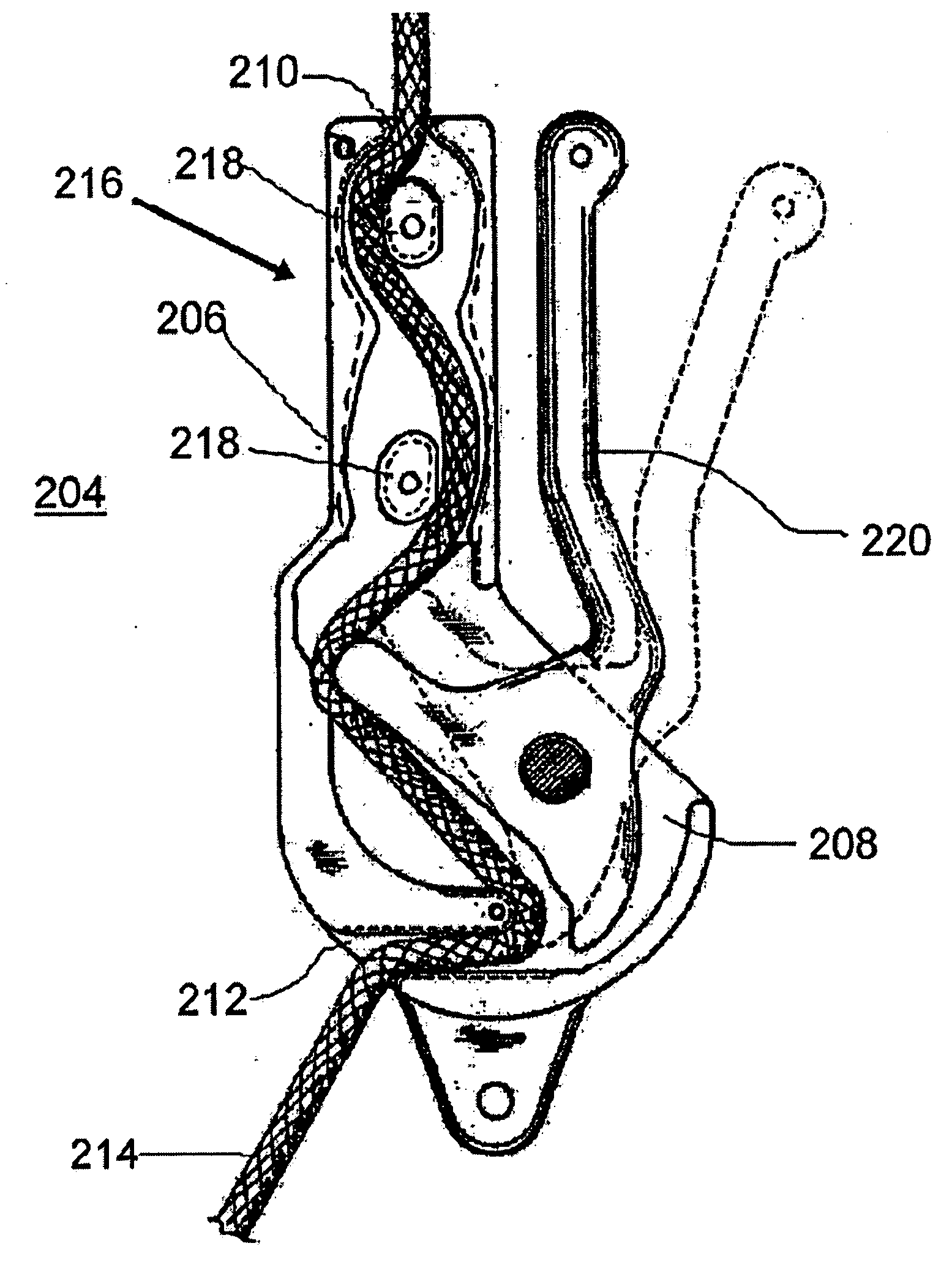
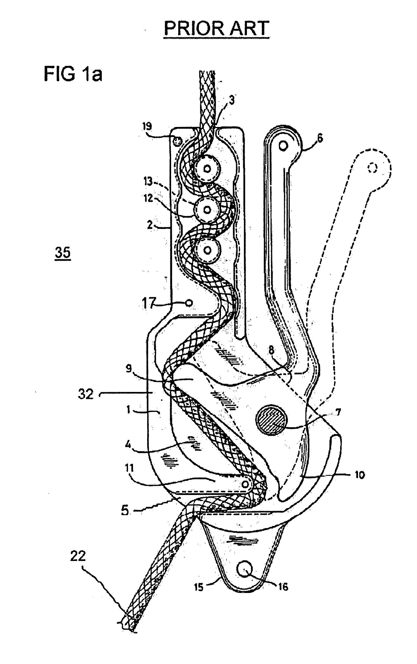
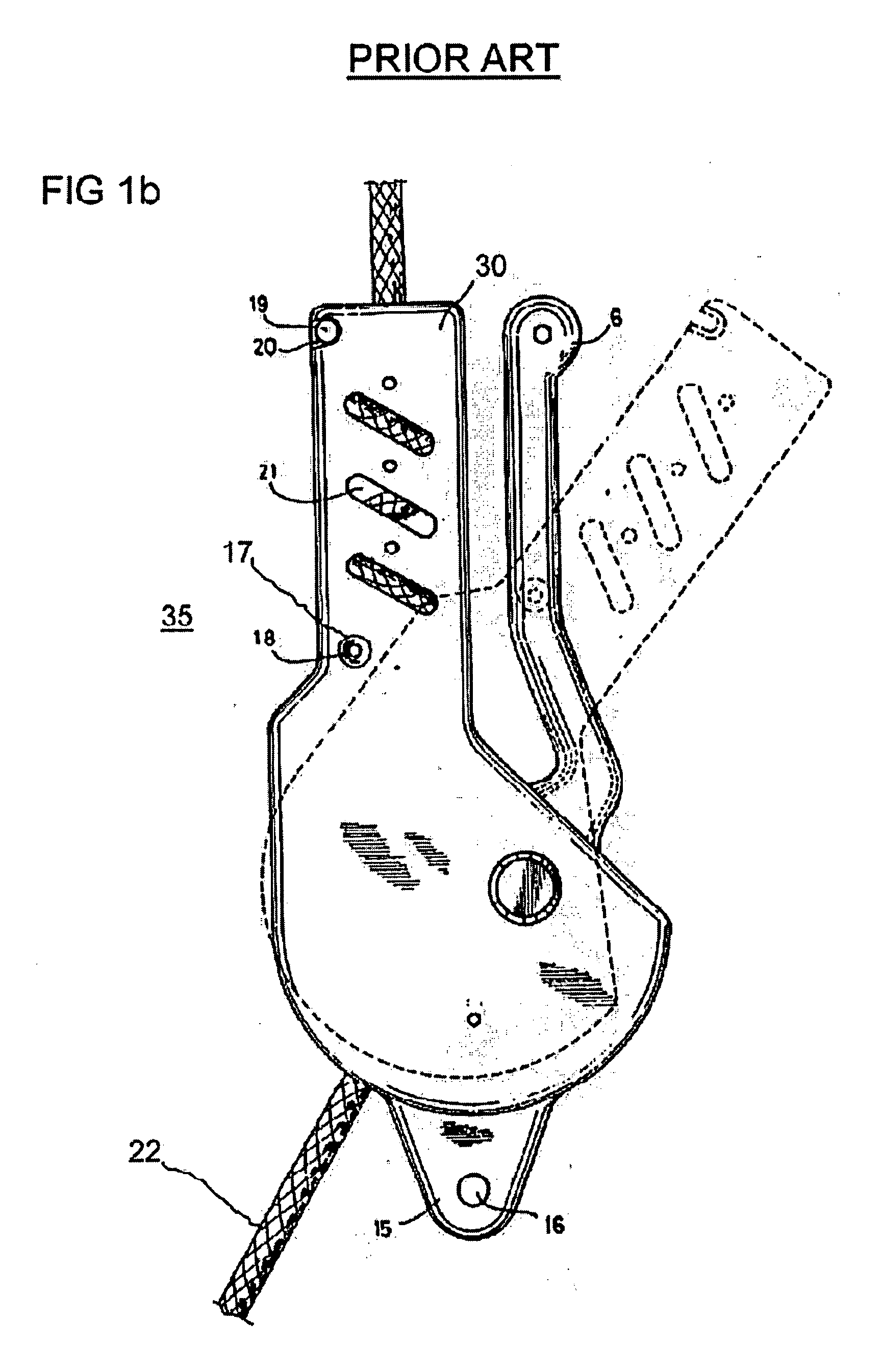
[0064] Reference is now made to FIG. 6a, which is an escape system 100 that is constructed and operable in accordance with a preferred embodiment of the present invention. Escape system 100 includes a control device 102 and an anchoring device 104. Control device 102 is configured for controlling the movement of a person (not shown) on a cord 106. The term “cord” is defined herein to include a line made of twisted fibers or threads, rope, cable, chain or any other equivalent elongated means for lowering and raising loads. Cord 106 is typically a cord having international standards certification, made from nylon or Kevlar or a cord having a steel core with a textile coating. Anchoring device 104 is configured for r...


PUM


Abstract

An escape system for moving a person on a cord on the exterior of a building. The building has a first surface and a second surface. The first surface and the second surface are substantially perpendicular to each other. The system comprises a control device for controlling the movement of the person on the cord and an anchoring device for reversibly mechanically attaching the control device to the building. The control device is substantially irreversibly mechanically connected to the anchoring device. The anchoring device has a first elongated element and a second elongated element. The first elongated is mechanically connected to the second elongated element. The first elongated element and the second elongated element are configured such that, the first elongated element at least partially rests against the first surface of the building and the second elongated element at least partially rests against the second surface of the building.

Description

FIELD AND BACKGROUND OF THE INVENTION [0001] The present invention relates to rescue systems and, in particular, it concerns a professional rescue system for escape from a building with a cord for use by military and civil rescue and evacuation forces. [0002] Of relevance to the present invention is U.S. Pat. No. 4,576,248 to Marom, which teaches a glider device for enabling a person to descend from a height in a controlled fashion. Reference is now made to FIGS. 1a and 1b, which show views of a glider device 35 of Marom. FIG. 1a is a plan view of glider device 35 with its cover removed that is constructed and operable in accordance with the prior art. FIG. 1b is an external plan view of glider device 35 of FIG. 1. Device 35 includes an elongated shallow housing 1, having a narrower top part 2 with an inlet 3 for a cable 22 and a wider bottom part 4 with an outlet 5 for cable 22. A substantially T-shaped lever 6 is pivotally attached at a point 7 within the bottom part 4 of housing ...

Claims


Application Information

Patent Timeline
Patent Type & Authority Applications(United States)
IPC IPC(8): A62B1/20
CPCA62B1/14E06B7/28
Inventor BARZILAI, YOAV
Owner BARZILAI YOAV
Why Eureka
Try Eureka