Magnetron sputtering device

a sputtering device and sputtering technology, applied in vacuum evaporation coatings, electrolysis components, coatings, etc., can solve the problems of high sputtering rate, high sputtering rate, and inability to achieve the degree of uniformity or repeatability required for many high-precision applications, so as to reduce cycle time, increase throughput, and increase production

Active Publication Date: 2006-04-06
VIAVI SOLUTIONS INC
View PDF24 Cites 15 Cited by
  • Summary
  • Abstract
  • Description
  • Claims
  • Application Information

AI Technical Summary

Benefits of technology

[0017] The present invention has realized increased production by reducing cycle time, thereby increasing throughput, rather than by increasing batch size. Further improvement in productivity is achieved by increasing product quality and uniformity. The present invention has found a geometry that increases coating rates through the use of a large cathode in conjunction with a planetary drive system, while maintaining low defect levels by lowering power density on the cathode. This is achieved by employing a new device geometry the device geometry between the cathode and substrate aligned to a central planetary axis.
[0023] a gas delivery system for providing a flow of sputter gas into the chamber, wherein the rotation radius of the planetary drive system and the throw distance are between half and twice the size of the planet diameter thereby providing minimized radial runoff of the coating quality without the use of a mask.

Problems solved by technology

This results in an increase in the gas atom-electron collision probability thereby leading to a much higher sputtering rate than that obtained without the use of magnetic confinement.
A limitation to the utility of planar and cylindrical magnetrons in either reactive or non-reactive sputtering is that films deposited by sputtering have not achieved the degree of uniformity or repeatability required for many high precision applications.
But over time the masks typically accumulate large amounts of coating material.
Once the material reaches a critical thickness it may flake off and contribute to particles that compromise the coating quality.
This geometry leads to low runoff without the use of a mask.
However, much coating material is wasted in this configuration.
The size of this device makes it difficult to maintain the drive system at good tolerances, causing variation in coating quality and runoff.
The attempt to increase production by increasing batch size is further limited by increased defect losses and reduced yield.

Method used


Image

  • Magnetron sputtering device
  • Magnetron sputtering device
  • Magnetron sputtering device

Examples


Embodiment Construction

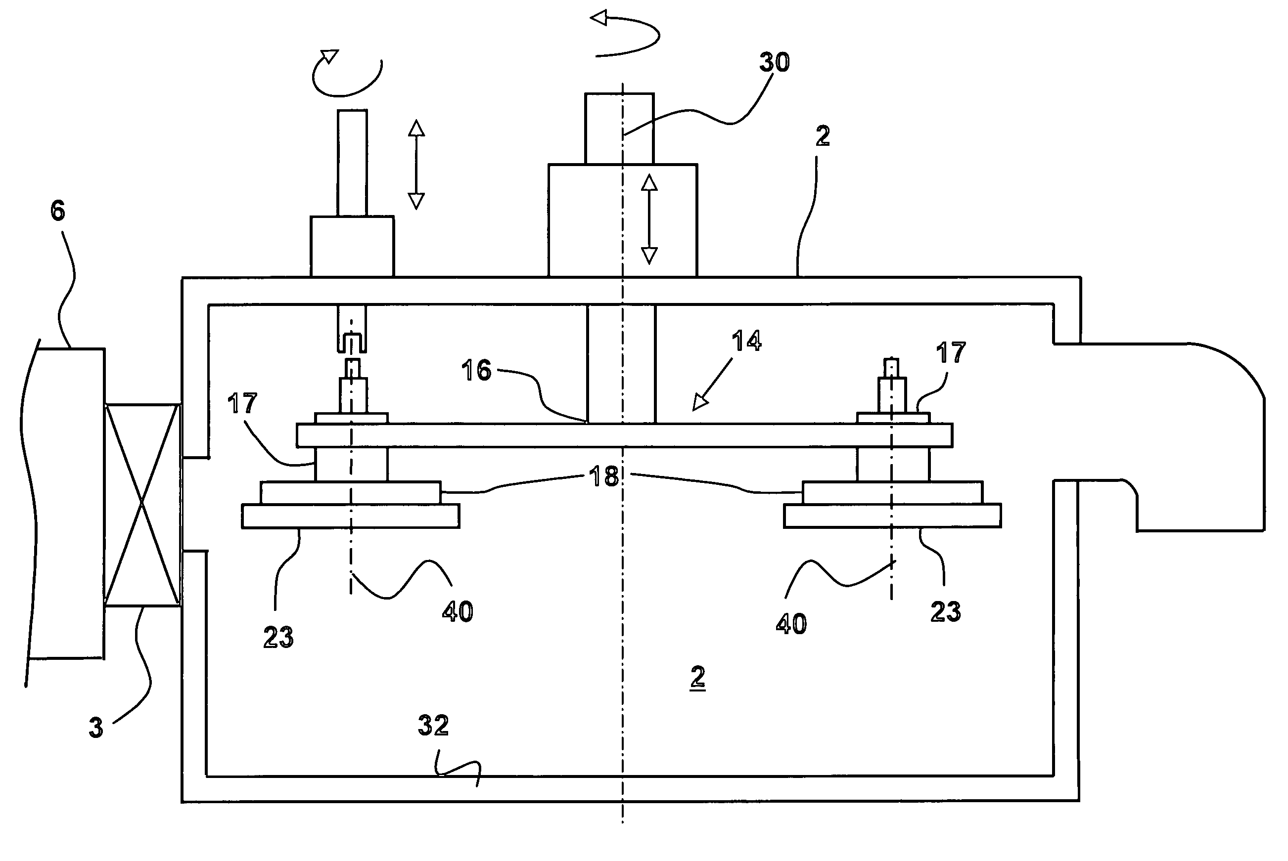
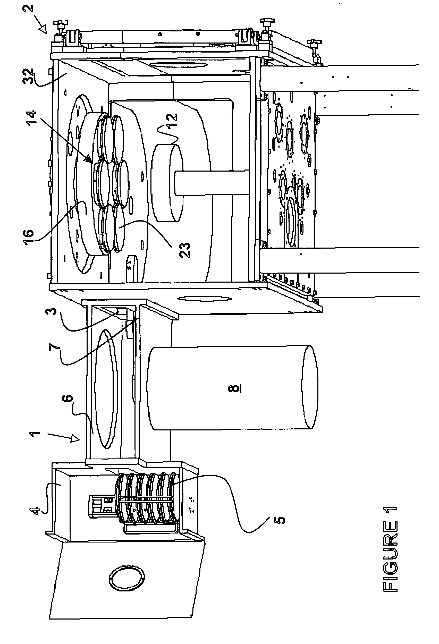
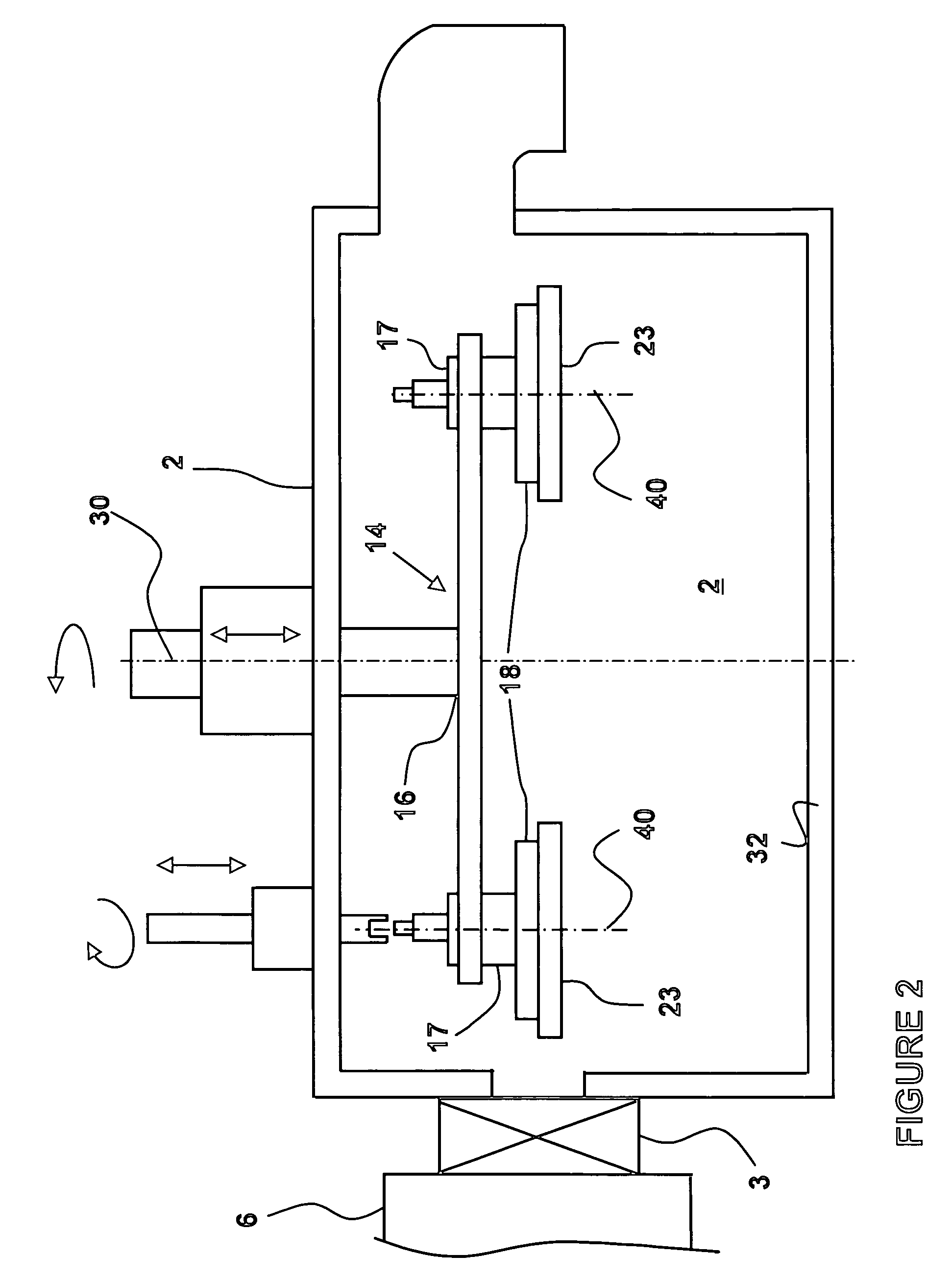
[0045] The present invention encompasses a unique geometry for a magnetron sputter coating device optimized to produce coatings at high coating rates with high throughput. This geometry effectively increases throughput by reducing cycle time. At the same time, the device geometry is guided by a need for high optical film quality and high precision. Optical films must have low defect levels, low scatter and absorption losses. High throughput depends also on high precision to prevent losses due to coating thickness variation, part to part variation or run to run variation.

[0046] Throughput can be defined as the load size per cycle time multiplied by the uptime percentage.

Throughput=Load Size / Cycle Time*Uptime Percentage

The load size of a coating chamber is the substrate area that is coated in one cycle of the machine. The cycle time of a coating machine is the time it takes to coat one batch of substrates or other objects and includes all ancillary processes prior to and also after ...


PUM

PropertyMeasurementUnit
diameteraaaaaaaaaa
diameteraaaaaaaaaa
diameteraaaaaaaaaa

Abstract

The present invention relates to a magnetron sputtering device and technique for depositing materials onto a substrate at a high production rate in which the deposited films have predictive thickness distribution and in which the apparatus can operate continuously and repeatedly for very long periods. The present invention has realized increased production by reducing cycle time. Increased coating rates are achieved by coupling a planetary drive system with a large cathode. The cathode diameter is greater than the diameter of a planet and less than twice the diameter of the planet. Lower defect rates are obtained through the lower power density at the cathode which suppresses arcing, while runoff is minimized by the cathode to planet geometry without the use of a mask.

Description

CROSS-REFERENCE TO RELATED APPLICATIONS [0001] This application claims priority from U.S. provisional application No. 60 / 603,211 filed Aug. 20, 2004, from U.S. application Ser. No. 11 / 074,249 filed on Mar. 7, 2005 and from U.S. application Ser. No. 11 / 177,465 filed Jul. 8, 2005, which are incorporated herein by reference for all purposes.FIELD OF THE INVENTION [0002] This invention relates generally to an apparatus and method for depositing films on a substrate, and more particularly to a magnetron sputtering device and technique for depositing materials onto substrates at a higher production rate, in which the deposited films have predictive thickness distribution with low defect levels and in which the apparatus can operate continuously and repeatedly for very long periods. BACKGROUND OF THE INVENTION [0003] In a sputtering deposition process ions are usually created by collisions between gas atoms and electrons in a glow discharge. The ions are accelerated into the target cathode...

Claims


Application Information

Patent Timeline
Patent Type & Authority Applications(United States)
IPC IPC(8): C23C14/00C25B11/00
CPCH01J37/32541H01J37/34H01J37/3438
Inventor TILSCH, MARKUS K.SEDDON, RICHARD I.OCKENFUSS, GEORG J.HAYES, JEREMYKLINGER, ROBERT E.
Owner VIAVI SOLUTIONS INC
Why Eureka
Try Eureka