Driving method and driving circuit for color liquid crystal display

a driving circuit and liquid crystal display technology, applied in the direction of instruments, television systems, static indicating devices, etc., can solve the problems of inability to meet the recent need of high video quality, inability to achieve optimal gamma compensation, and inability to obtain a good gradation reproduced image, etc., to achieve high transmittance characteristics, reduce circuit scale, and high quality

Inactive Publication Date: 2006-04-06
VISTA PEAK VENTURES LLC
View PDF6 Cites 6 Cited by
  • Summary
  • Abstract
  • Description
  • Claims
  • Application Information

AI Technical Summary

Benefits of technology

[0077] Also, since the color liquid crystal display is driven based on the compensated video red signal, the compensated video green signal and the compensated video blue signal obtained by independently applying gamma compensations to the video red signal, the video green signal and the video blue signal so as to be suitable to the red transmittance characteristic, the green transmittance characteristic and the blue transmittance characteristic for an applied voltage to the color liquid crystal display, it is possible to carry out an optimal gamma compensation fully suitable to a characteristic of the color liquid crystal display. Thus, it is possible to fully meet a recent need of a high quality image. Also, it is possible to use a color liquid crystal display having a high transmittance characteristic in which maximum luminance are very different concerning red, green and blue. Furthermore, though the gradation batter occurs in a specific color among red, green and blue, a voltage for the gamma compensation concerning the specific color can be changed, therefore, it is possible to remove the gradation batter of the specific color.
[0078] Also, using the common voltage or the common data, the gamma compensation can be applied to the video red signal, the video green signal and the video blue signal corresponding to an area in which characteristic curves become an approximately similar form in the red transmittance characteristic, the green transmittance characteristic and blue transmittance characteristic, therefore, it is possible to reduce a circuit scale.
[0079] Further, the first gamma compensating section, the second gamma compensating section and the third gamma compensating section previously memorize the compensated red data, the compensated green data and the compensated blue data corresponding red data, green data and blue data, read the corresponding compensated red data, the corresponding compensated green data and the corresponding compensated blue data using the red data, the green data. And then, the first gamma compensating section, the second gamma compensating section and the third gamma compensating section apply the blue data as reference addresses and the gamma compensation, it is possible to execute the gamma compensation at higher speed.

Problems solved by technology

However, particularly in the green (curve b), a white level is set at transmittance of 80%, therefore, it is impossible to carry out an optimal gamma compensation and then it is impossible to obtain a reproduced image of a good gradation.
As a result, there a disadvantage in that it is impossible to meet a recent need of a high video quality.
In such the V-T characteristic curve, each of red (curve a), green (curve b) and blue (curve c) has a transmittance of 100%, namely, each best luminance is too different, therefore, there is a problem in that the color liquid crystal display 1 cannot be used since it is impossible to deal with gamma characteristics of the conventional gamma compensation which are used in common with red, green and blue.
Furthermore, as above described, in the first conventional example and the second conventional example of a driving circuit for the color liquid crystal display, gamma compensation is applied based on common reference voltage VL, common reference voltage VM and common reference voltage VH or a common group of gradation voltage V0 to gradation voltage V4 and a common group of gradation voltage V5 to gradation voltage V9, therefore, there is a problem in that, though a gradation batter occurs in which gradation change is not displayed on a display as luminance changes, the gradation batter can not be removed.

Method used


Image

  • Driving method and driving circuit for color liquid crystal display
  • Driving method and driving circuit for color liquid crystal display
  • Driving method and driving circuit for color liquid crystal display

Examples


first embodiment

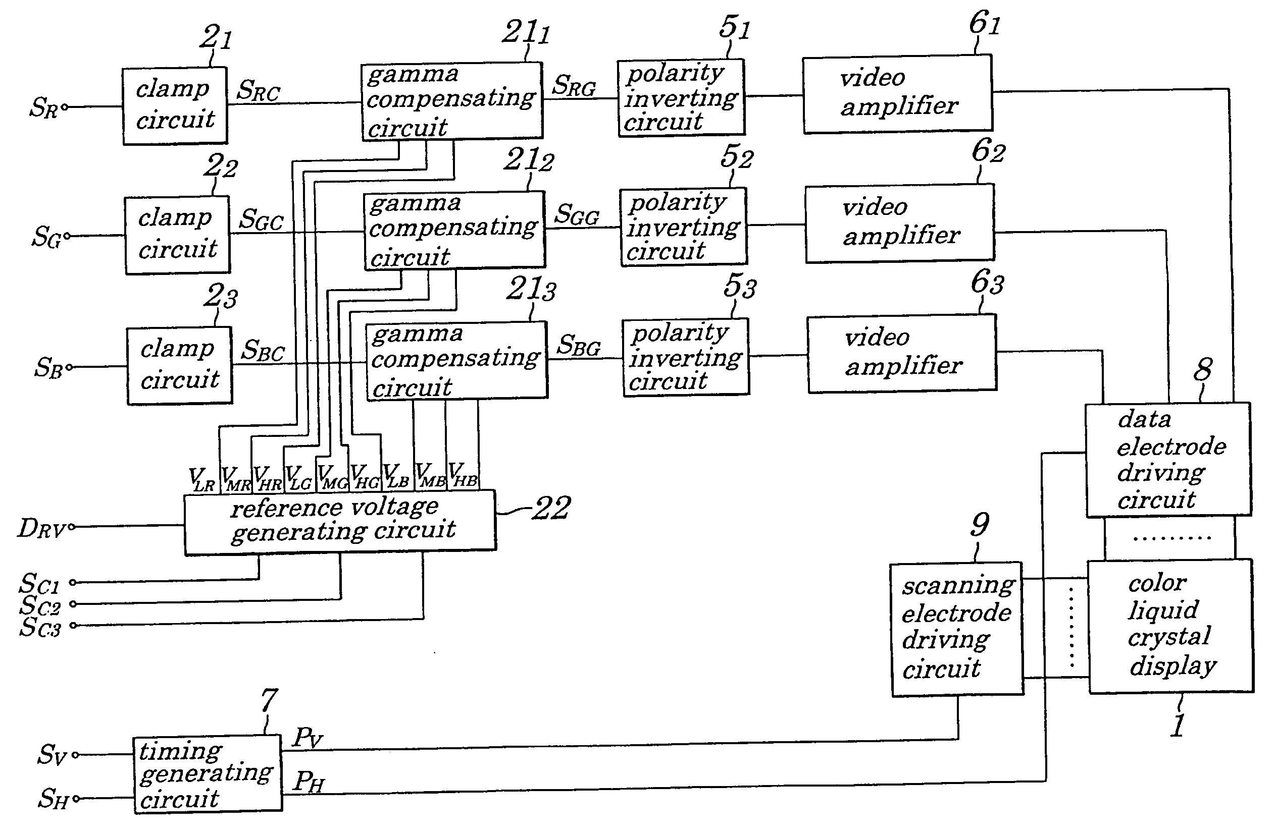
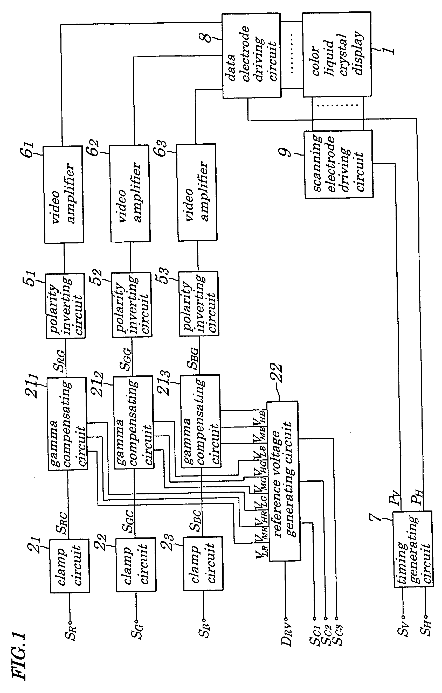
[0106]FIG. 1 is a block diagram showing an electrical configuration of a driving circuit of an analog circuit configuration for a color liquid crystal display 1 according to a first embodiment of the present invention. In FIG. 1, the color liquid crystal display 1 is a liquid crystal display of an active matrix driving type using a TFT (Thin Film Transistor) as a switching element.

[0107] The driving circuit of the color liquid crystal display 1 is mainly provided with clamp circuit 21 to clamp circuit 23, a reference voltage generating circuit 22, gamma compensating circuit 211 to gamma compensating circuit 213, polarity inverting circuit 51 to polarity inverting circuit 53, video amplifier 61 to video amplifier 63, a timing generating circuit 7, a data electrode driving circuit 8 and a scanning electrode driving circuit 9. That is, the reference voltage generating circuit 22, and gamma compensating circuit 211 to gamma compensating circuit 213 are provided instead of the reference...

second embodiment

[0130] Next, explanations will be given of the second embodiment according to the present invention.

[0131]FIG. 6 is a block diagram showing an electrical configuration of a driving circuit for the color liquid crystal display 1 according to the second embodiment of the present invention. In FIG. 6, same numerals are given to corresponding parts in FIG. 1 and the explanations thereof are omitted. In the driving circuit for the color liquid crystal display 1 shown in FIG. 6, instead of the reference voltage generating circuit 22 shown in FIG. 1, a reference voltage generating circuit 31 is provided.

[0132]FIG. 7 is a block diagram showing one example of an electrical configuration of the reference voltage generating circuit 31. In FIG. 7, same numerals are given to corresponding parts in FIG. 3 and the explanations thereof are omitted. In the reference voltage generating circuit 31 shown in FIG. 7, instead of the DAC 25 and the reference voltage supply source 26 shown in FIG. 3, a DA...

third embodiment

[0138] Next, explanations will be given of the third embodiment of the present invention.

[0139]FIG. 8 is a block diagram showing an electrical configuration of a driving circuit of a digital circuit configuration for a color liquid crystal display 1 according to the third embodiment of the present invention. In FIG. 8, same numerals are given to corresponding parts in FIG. 20 and the explanations thereof are omitted.

[0140] In the driving circuit for the color liquid crystal display 1 shown in FIG. 8, instead of a controlling circuit 11, a gradation power supply circuit 12 and a data electrode driving circuit 13 shown in FIG. 20, a controlling circuit 41, a gradation power supply circuit 42 and a data electrode driving circuit 43 are provided.

[0141] The controlling circuit 41 is, for example, an ASIC, and supplies red data DR of eight bits, green data DG of eight bits, blue data DB of eight bits supplied from outside to the data electrode driving circuit 43 and generates a polarit...


PUM

PropertyMeasurementUnit
inclination angleaaaaaaaaaa
transmittanceaaaaaaaaaa

Abstract

A driving method for a color liquid crystal display which drives the color liquid crystal display based on a video red signal, a video green signal and a video blue signal by independently applying a gamma compensation to a clamped video red signal, a clamped video green signal and a clamped video blue signal in gamma compensating circuits in order to make suitable to a red transmittance characteristic, a green transmittance characteristic and a blue transmittance characteristic. With this operation, it is possible to carry out an optimal gamma compensation suitable to a characteristic of the color liquid crystal display and to remove a gradation batter occurring in a specific color.

Description

CROSS REFERENCE TO RELATED APPLICATION [0001] This application is a divisional of co-pending U.S. patent application Ser. No. 09 / 707,816, filed Nov. 7, 2000.BACKGROUND OF THE INVENTION [0002] 1. Field of the Invention [0003] The present invention relates to a driving method and a driving circuit for a color liquid crystal display and more particularly to the driving method and the driving circuit for driving the color liquid crystal display based on a gamma compensated video signal. [0004] The present application claims the Convention Priority of Japanese Patent Application No. Hei11-316873 filed on Nov. 8, 1999, which is hereby incorporated by reference. [0005] 2. Description of the Related Art [0006]FIG. 19 is a block diagram showing a conventional electric configuration of a driving circuit of an analog circuit configuration of a color liquid crystal display 1. [0007] The color liquid crystal display 1 is a liquid crystal display of an active matrix driving type using a TFT (Thin...

Claims


Application Information

Patent Timeline
Patent Type & Authority Applications(United States)
IPC IPC(8): G09G3/36G02F1/133G09G3/20
CPCG09G3/3614G09G3/3688G09G2310/027G09G2310/0297G09G2320/0276G09G3/36
Inventor SUGAWARA, NORIAKIKOGA, KOUICHI
Owner VISTA PEAK VENTURES LLC
Why Eureka
Try Eureka