Method and apparatus for creating an image on an article, and article resulting therefrom

a technology of image and article, applied in the field of printing an image on an object, can solve the problems of lack of natural wood, high cost of natural wood items, and inability to achieve the appearance of natural wood, and achieve the effect of enhancing natural wood

Inactive Publication Date: 2006-04-06
MASONITE CORP
View PDF14 Cites 24 Cited by
  • Summary
  • Abstract
  • Description
  • Claims
  • Application Information

AI Technical Summary

Benefits of technology

[0014] The present invention is related to a method of printing an image on an article, such as a wood grain pattern on a door skin, an apparatus for printing, and the resulting printed article. The invention is also related to an image processing apparatus for creating an image to be printed. The method and apparatus may be utilized to create various decorative products, such as millwork, molding, plant-on panels, closet or wardrobe doors, molded wainscot, decorative cabinet doors, and exterior polymeric doors. The method may also be used to enhance natural wood and veneer faced surfaces.
[0015] The images are printed on the article using an ink jet printer, which provides great flexibility in what can be printed. Different products, for example those with a short product life for which the making of a specific print roller might not have been justified, can now easily be printed using the disclosed ink jet technique. Customized objects, such as simulated wood species and decorative graphic images, can be produced quickly and cheaply. Printing a wood grain pattern onto an article using an ink jet printer has been found to give a good result easily and relatively cheaply compared with the use of a wood or simulated wood veneer. As used herein, the term “wood grain” includes any pattern resembling a feature of wood grain, preferably of any type of wood.
[0016] The disclosed method may be used to print on a part of a surface of an article. For example, a simulated wood region may form only a part of an object, for example a frame of a framed picture. Ink jet printing provides the flexibility to print in register on small areas of an object.

Problems solved by technology

Solid, natural wood is a relatively expensive material, and thus items made from natural wood are generally more expensive than items made from alternative materials such as plastic or wood composite.
Wood composite articles, such as door skins, are somewhat similar to natural wood in strength and density, but lack the appearance of natural wood, especially the color, grain and / or inlay patterns that are considered desirable by many consumers.
However, the application of veneers, papers and foils is often time consuming, and, especially in the case of papers and foils, can produce an unacceptable product if great care is not taken in the application of the materials.
This increases the manufacturing cost of such articles and results in varied aesthetics.
However, such printing methods are generally complex, and require the use of a different set of rollers or cylinders for each desired pattern or for differently shaped articles being printed.
In addition, the engraved cylinders and rollers are relatively expensive, but not overly reliable to hold close register.
However, prior art ink jet printing methods have failed to achieve satisfactory image quality on a printed article, particularly when printing on fiberboard.
While it may sometimes be possible to produce low-resolution simulated wood grain on planar surfaces, such as flush door skins, it has heretofore not been possible to produce high-quality images directly on contoured surfaces.
Instead, when high quality images are needed, it is necessary to print such images on paper or film and then attach the paper or film to the surface of the substrate in a labor-intensive lamination step.
Moreover, on contoured surfaces, such as molded door skins, it has not heretofore been possible to produce either a realistic wood grain or other images in the recessed and / or raised contoured portions of the skin.
If the feature is a recessed portion, such as a molded channel, additional problems arise using the method disclosed by Kubo.
First, the width of the channel may be less than the width of the printhead, making it impossible to lower the printhead into the channel to maintain the required spacing between the printhead and the surface being printed.
Second, turbulence surrounding ejected droplets of ink may be magnified by the narrow channel, making it difficult to control the placement of ink droplets.
Increasing the distance between the printhead and recessed portions of a surface to be printed, to overcome problems associated with Kubo, have also failed to achieve a adequate quality image.
One of the problems of increasing the distance of travel of the ink droplets in the region of a recess is that after a short distance of travel from the printhead nozzles, there is breaking of the droplets due to the viscosity of the air and the relatively small size of the droplets.
As the droplets lose momentum, they become increasingly susceptible to air currents that move the droplets away from their intended path.
This ultimately leads to errors in droplet placement and thus reduction in image quality.
This affects droplet placement and image quality.
This effect can act as an “air pump,” causing the droplets at the edge of the curtain to be pulled in towards the other droplets, causing turbulence and droplet interaction.
Droplet placement and image quality may be adversely affected.
Furthermore, if the article to be printed is moving relative to the printhead, there may be additional detrimental effects on droplet placement.
All of these effects combine to reduce print quality.

Method used


Image

  • Method and apparatus for creating an image on an article, and article resulting therefrom
  • Method and apparatus for creating an image on an article, and article resulting therefrom
  • Method and apparatus for creating an image on an article, and article resulting therefrom

Examples


Embodiment Construction

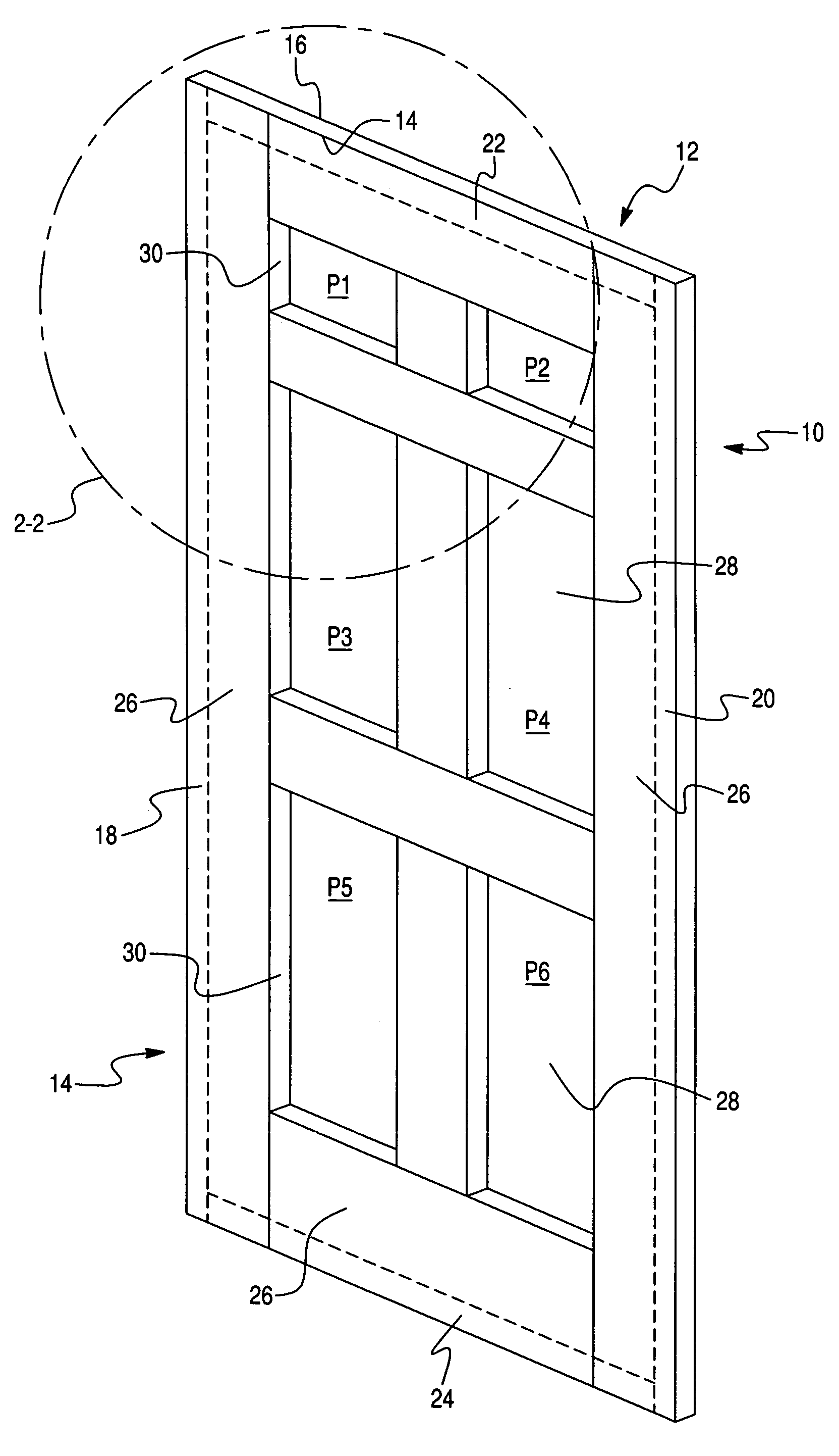
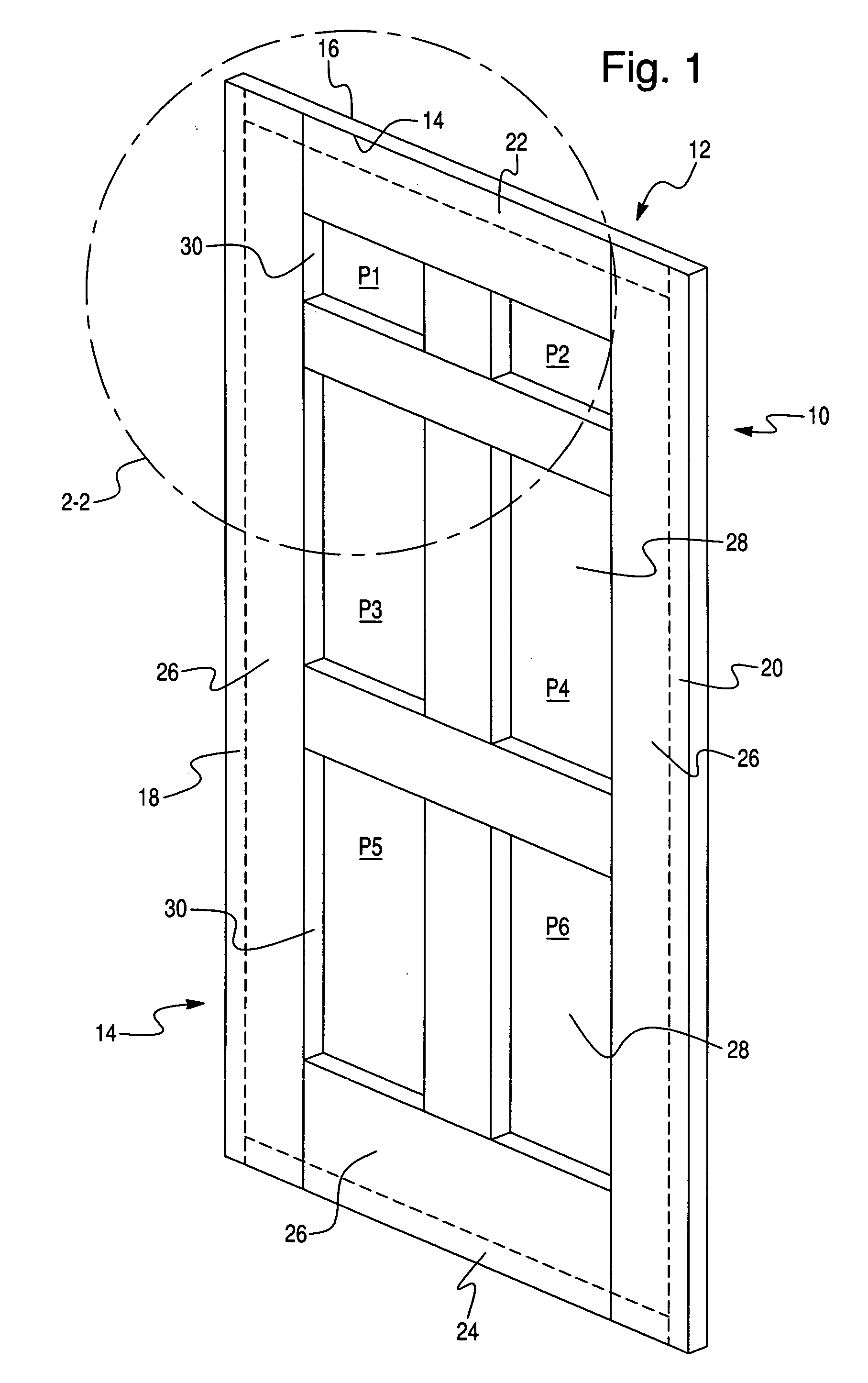
[0051] The present invention is directed to a method and apparatus for creating an image on an article, such as a simulated wood grain pattern on a door skin, using an ink jet printer. Any object that can be printed using ink jet printing is suitable for the disclosed invention. Preferably, the printed object includes hard rigid surfaces, although other surfaces such as wood veneer or paper overlaid wood composites, are also suitable.

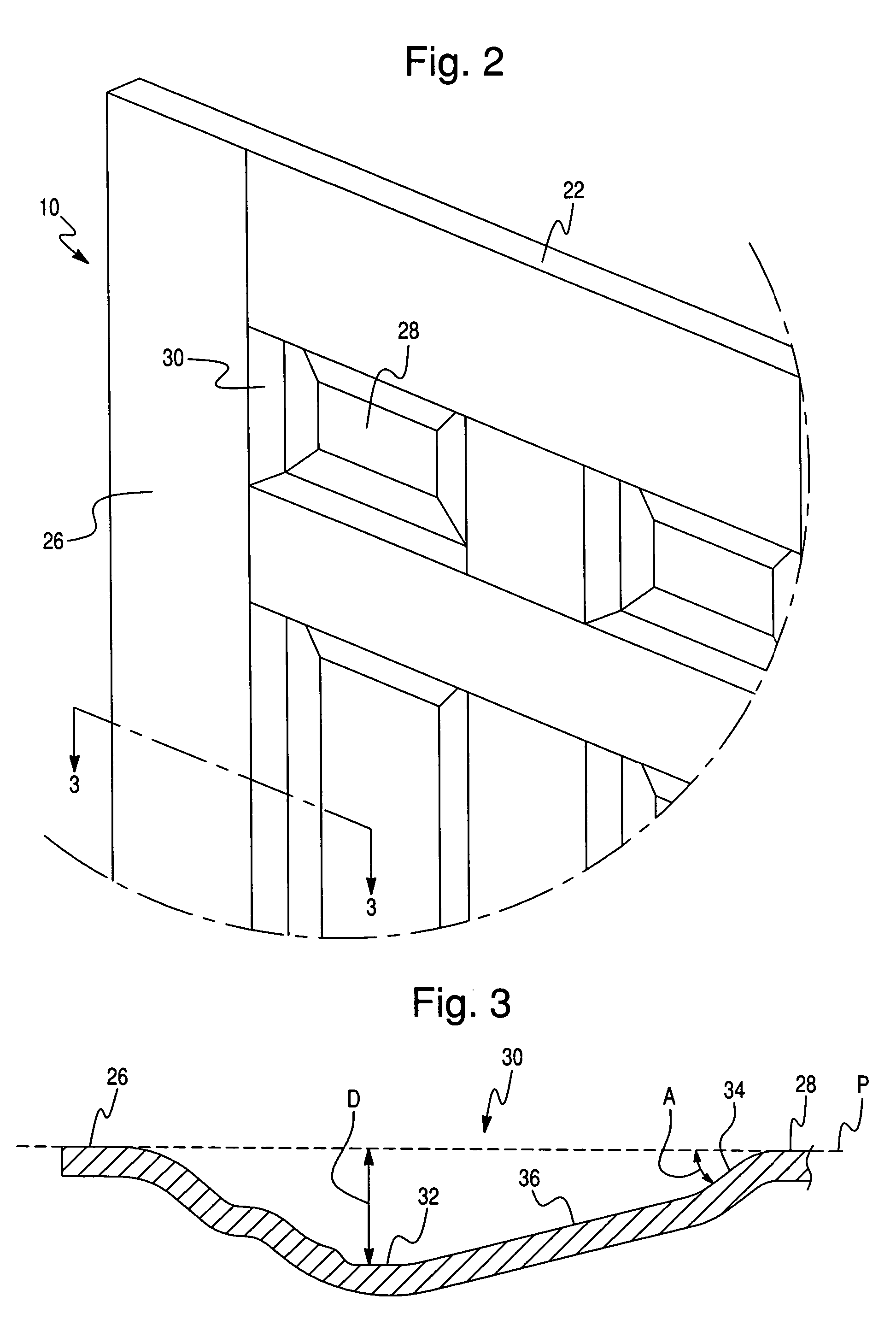
[0052] The printed object preferably comprises a three-dimensional object, such as one or more of furniture, a fixture and / or a fitting, and / or a fixed construction. The surface of such an object preferably includes at least one recess and / or projection. Prior attempts to print on uneven surfaces using an ink jet technique achieved unacceptable results due to the variation in distance of the substrate from the printhead. However, the disclosed printing technique achieves images having surprisingly high quality.

[0053] Examples of suitable objects to be...


PUM

PropertyMeasurementUnit
diameteraaaaaaaaaa
diameteraaaaaaaaaa
constant distanceaaaaaaaaaa

Abstract

A method of printing an image on an object comprises the steps of: providing an object having an exterior surface having a planar portion and a channel recessed from the planar portion; applying a first ground coat on the exterior surface; drying the first ground coat; and spraying droplets of ink on the dried ground coat to form an image, wherein the droplets are sprayed from an ink jet printhead that is maintained at a constant distance from the plane of the planar portion of the object.

Description

CROSS REFERENCE TO RELATED APPLICATIONS AND CLAIM TO PRIORITY [0001] The present application claims the benefit under 35 U.S.C. § 120 of U.S. Provisional Patent Application Ser. No. 60 / 369,798, filed Apr. 3, 2002, titled “Method and Apparatus for Printing an Object”, the disclosure of which is hereby incorporated by reference.FIELD OF THE INVENTION [0002] The present invention is directed to a method of printing an image on an object, comprising the steps of: providing an object having an exterior surface having a planar portion and a channel recessed from the planar portion; applying a first ground coat on the exterior surface; drying the first ground coat; and spraying droplets of ink on the dried ground coat to form an image, wherein the droplets are sprayed from an ink jet printhead that is maintained at a constant distance from the plane of the planar portion of the object. The invention also relates to an object having an image created according to the disclosed method, and a ...

Claims


Application Information

Patent Timeline
Patent Type & Authority Applications(United States)
IPC IPC(8): B41J2/01B41J3/407B41M5/00B41J11/00
CPCB41J3/4073B41J11/0015B41M5/0011B41M5/0047B41M5/0058B41M5/0088B44C5/043B44F9/02B41J2/01
Inventor BAXTER, WILLIAM R.S.EVE, RICHARD W.LUETGERT, KARINE A.FELLIN, SCOTT
Owner MASONITE CORP
Why Eureka
Try Eureka