Solid, natural wood is a relatively expensive material, and thus items made from natural wood are generally more expensive than items made from alternative materials such as plastic or wood composite.
Wood composite articles, such as door skins, are somewhat similar to natural wood in strength and density, but lack the appearance of natural wood, especially the color, grain and / or inlay patterns that are considered desirable by many consumers.
However, the application of veneers, papers and foils is often
time consuming, and, especially in the case of papers and foils, can produce an unacceptable product if great care is not taken in the application of the materials.
This increases the manufacturing cost of such articles and results in varied aesthetics.
However, such printing methods are generally complex, and require the use of a different set of rollers or cylinders for each desired pattern or for differently shaped articles being printed.
In addition, the engraved cylinders and rollers are relatively expensive, but not overly reliable to hold close register.
However, prior art ink jet printing methods have failed to achieve satisfactory
image quality on a printed article, particularly when printing on
fiberboard.
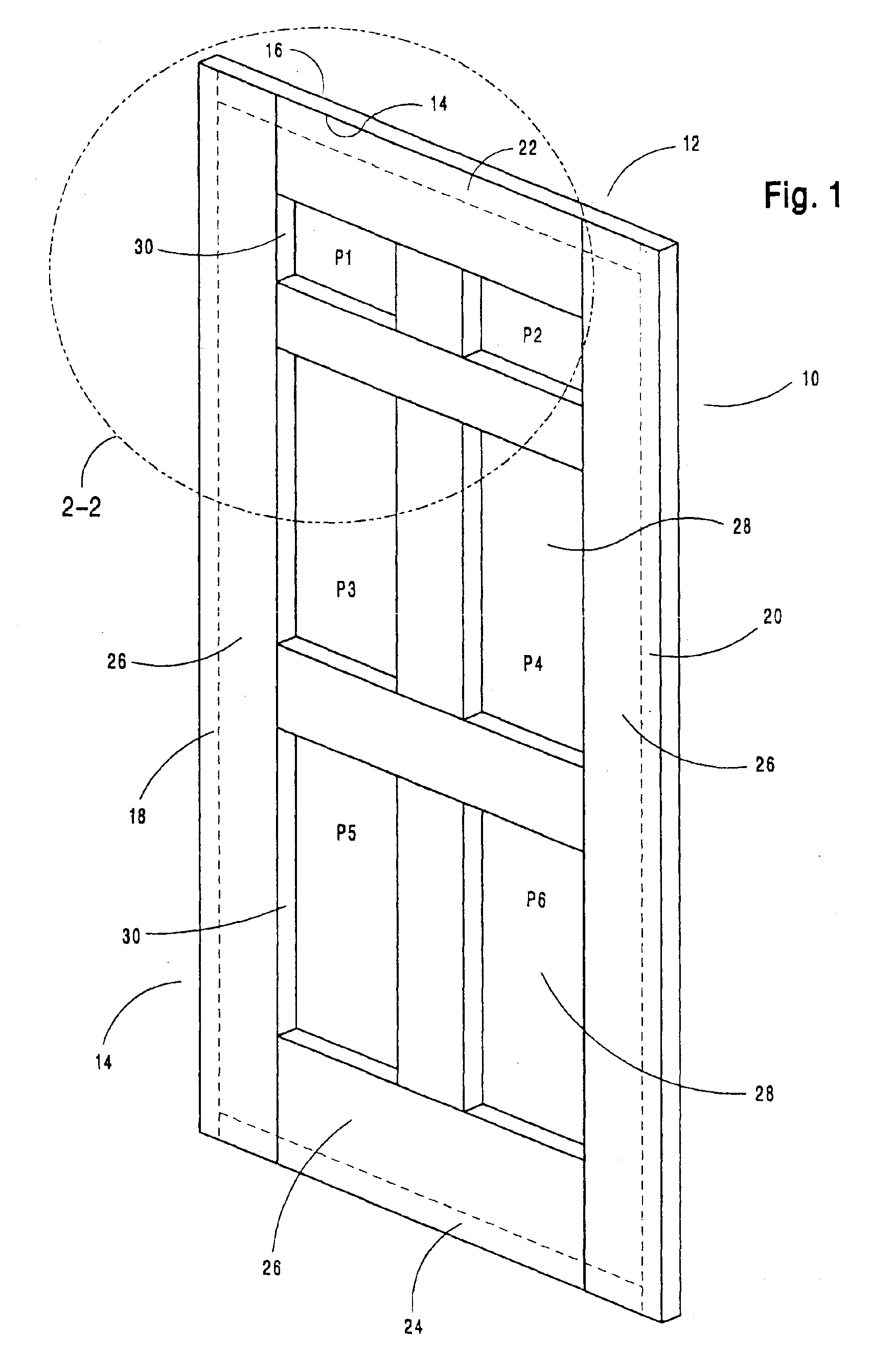
While it may sometimes be possible to produce low-resolution simulated
wood grain on planar surfaces, such as flush door skins, it has heretofore not been possible to produce high-quality images directly on contoured surfaces.
Instead, when high quality images are needed, it is necessary to print such images on paper or film and then attach the paper or film to the surface of the substrate in a labor-intensive lamination step.
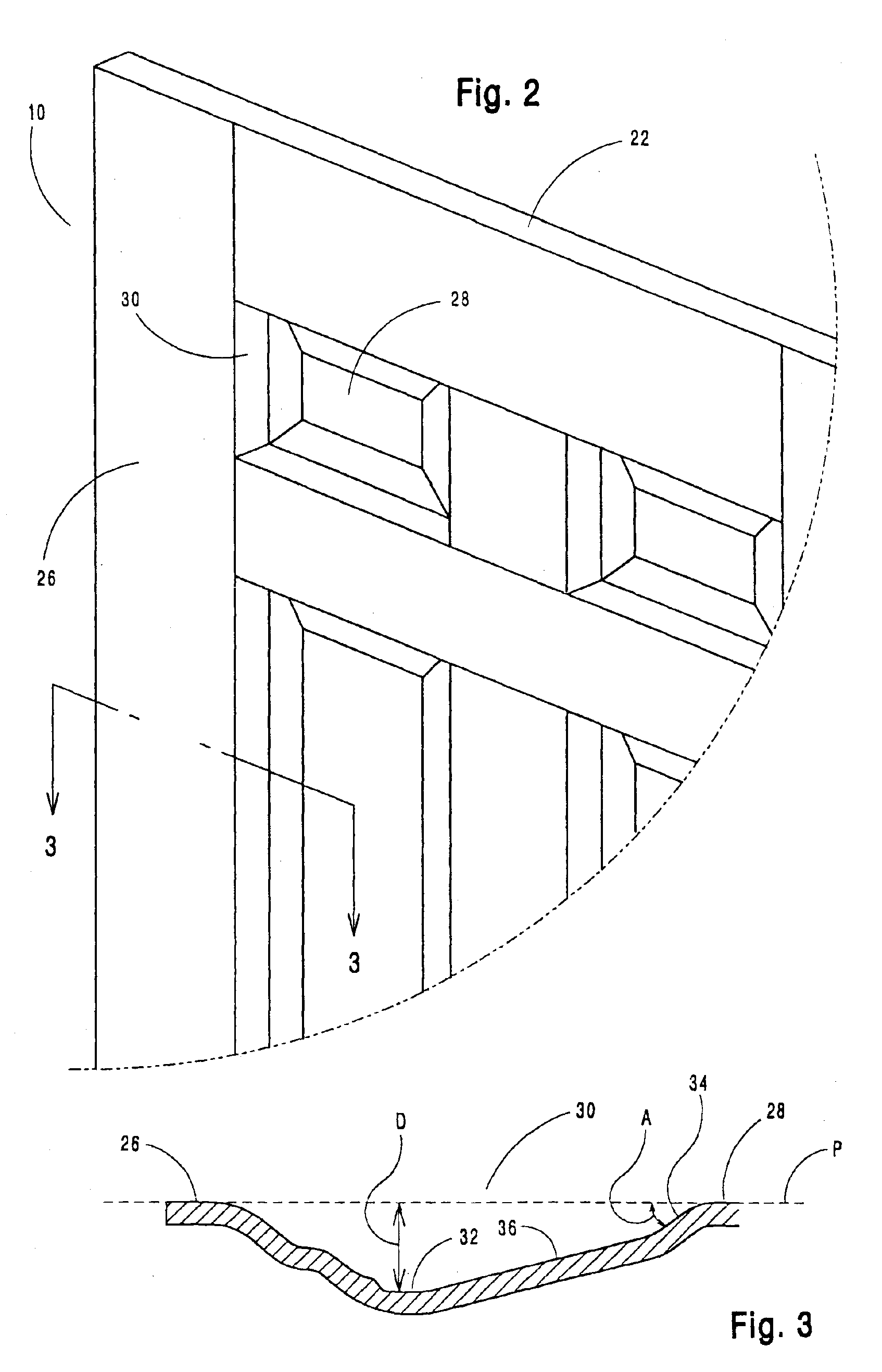
Moreover, on contoured surfaces, such as molded door skins, it has not heretofore been possible to produce either a realistic
wood grain or other images in the recessed and / or raised contoured portions of the
skin.
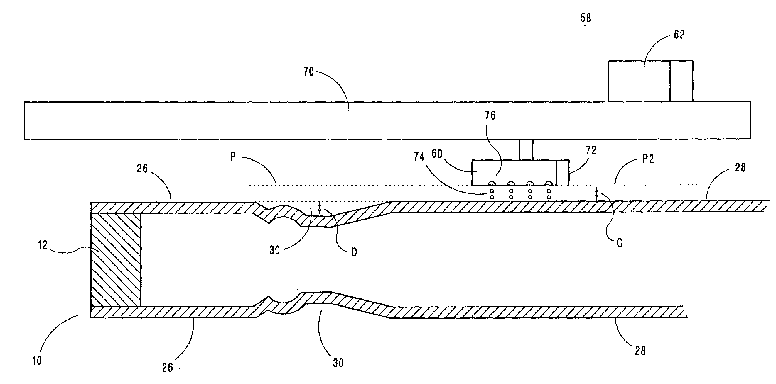
If the feature is a recessed portion, such as a molded channel, additional problems arise using the method disclosed by Kubo.
First, the width of the channel may be less than the width of the printhead, making it impossible to lower the printhead into the channel to maintain the required spacing between the printhead and the surface being printed.
Second, turbulence surrounding ejected droplets of ink may be magnified by the
narrow channel, making it difficult to control the placement of ink droplets.
Increasing the distance between the printhead and recessed portions of a surface to be printed, to overcome problems associated with Kubo, have also failed to achieve a adequate quality image.
One of the problems of increasing the distance of travel of the ink droplets in the region of a recess is that after a
short distance of travel from the printhead nozzles, there is breaking of the droplets due to the
viscosity of the air and the relatively small size of the droplets.
As the droplets lose
momentum, they become increasingly susceptible to air currents that move the droplets away from their intended path.
This ultimately leads to errors in droplet placement and thus reduction in
image quality.
This effect can act as an “
air pump,” causing the droplets at the edge of the curtain to be pulled in towards the other droplets, causing turbulence and droplet interaction.
Droplet placement and image quality may be adversely affected.
Furthermore, if the article to be printed is moving relative to the printhead, there may be additional detrimental effects on droplet placement.
All of these effects combine to reduce print quality.

