
Image input device

a technology of input device and image, which is applied in the direction of optical radiation measurement, instruments, television systems, etc., can solve the problems of reducing image resolution and achieving the effect of high-quality images

Inactive Publication Date: 2006-04-06
KONICA MINOLTA INC
View PDF9 Cites 225 Cited by
  • Summary
  • Abstract
  • Description
  • Claims
  • Application Information

AI Technical Summary

Benefits of technology

[0015] According to the said construction, even if the distance between micro-lens and the subject is infinitely long, the object reduced images focused on the light detecting element can be differed at every micro-lenses, furthermore, the resolution of the reconfigured image obtained by the rearrangement of image information of the object reduced images can be increased.
[0017] According to the foregoing system, since the said relative position is adjusted corresponding to the distance to the subject (i.e. magnification), it is capable of focusing the different object reduced image on the light detecting element consistently, irrespective of the distance to the subject, and moreover, the resolution of the single reconfigured image obtained by the rearrangement of image information of the object reduced images can be increased. More details will hereinafter be described.
[0019] Accordingly, the resolution of the said object image can be improved using the difference of the said object reduced images arising from the difference between the said relative positions by fixing the rearranged position of pixel information of the said reduced-images.
[0021] In the foregoing construction, as will hereinafter described, it is capable of making the decreasing degree of resolution to the minor even when the distance to the subject changes, and its convenience as an image input apparatus can be improved.
[0023] Accordingly, it is capable of obtaining the object image in colors from the object reduced images focused on the said light detecting element, thereby realizing the image input apparatus which can obtain more high-quality images. As such construction can be realized from the basis of conventional systems, it is also excellent from the view that the rising of manufacturing cost is controlled to the minimum.

Problems solved by technology

This creates the problem of remarkable decrease of image resolution compared to the case when taking an image of close subject (when there is a parallax between said micro-lenses).

Method used


Image

  • Image input device
  • Image input device
  • Image input device

Examples


Embodiment Construction

[0037] With embodiments of the present invention described hereinafter with reference to the accompanying drawings, it is to be understood that the invention is not limited to those precise embodiments, and that various changes and modifications may be effected therein by one skilled in the art without departing from the scope or spirit of the invention as defined in the appended claims.

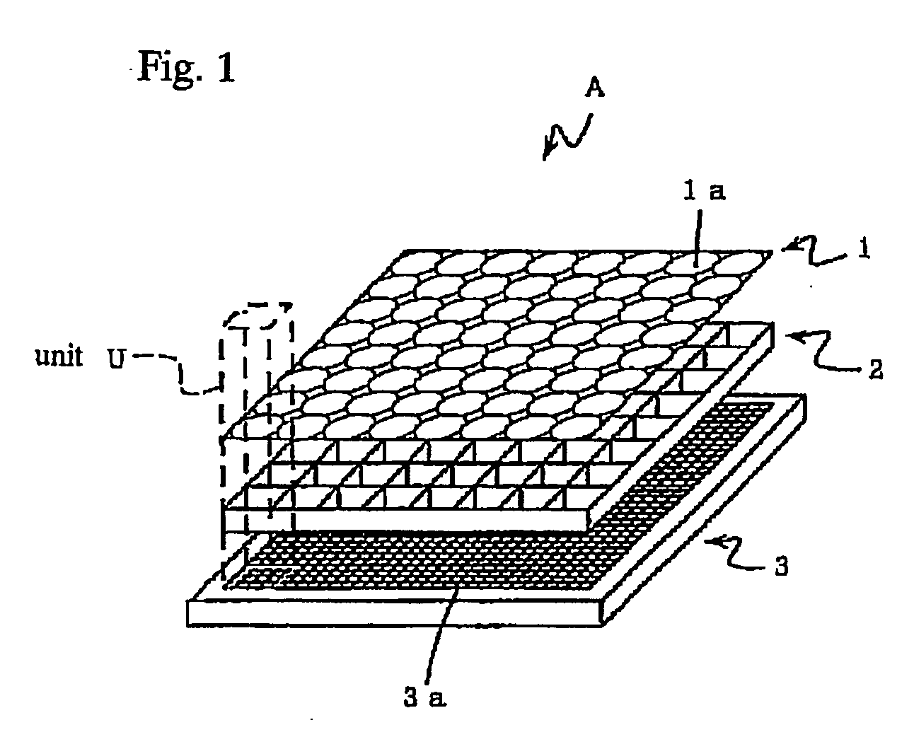
[0038] The image input apparatus according to the embodiments of the present invention is embodied as indicated in FIG. 1.

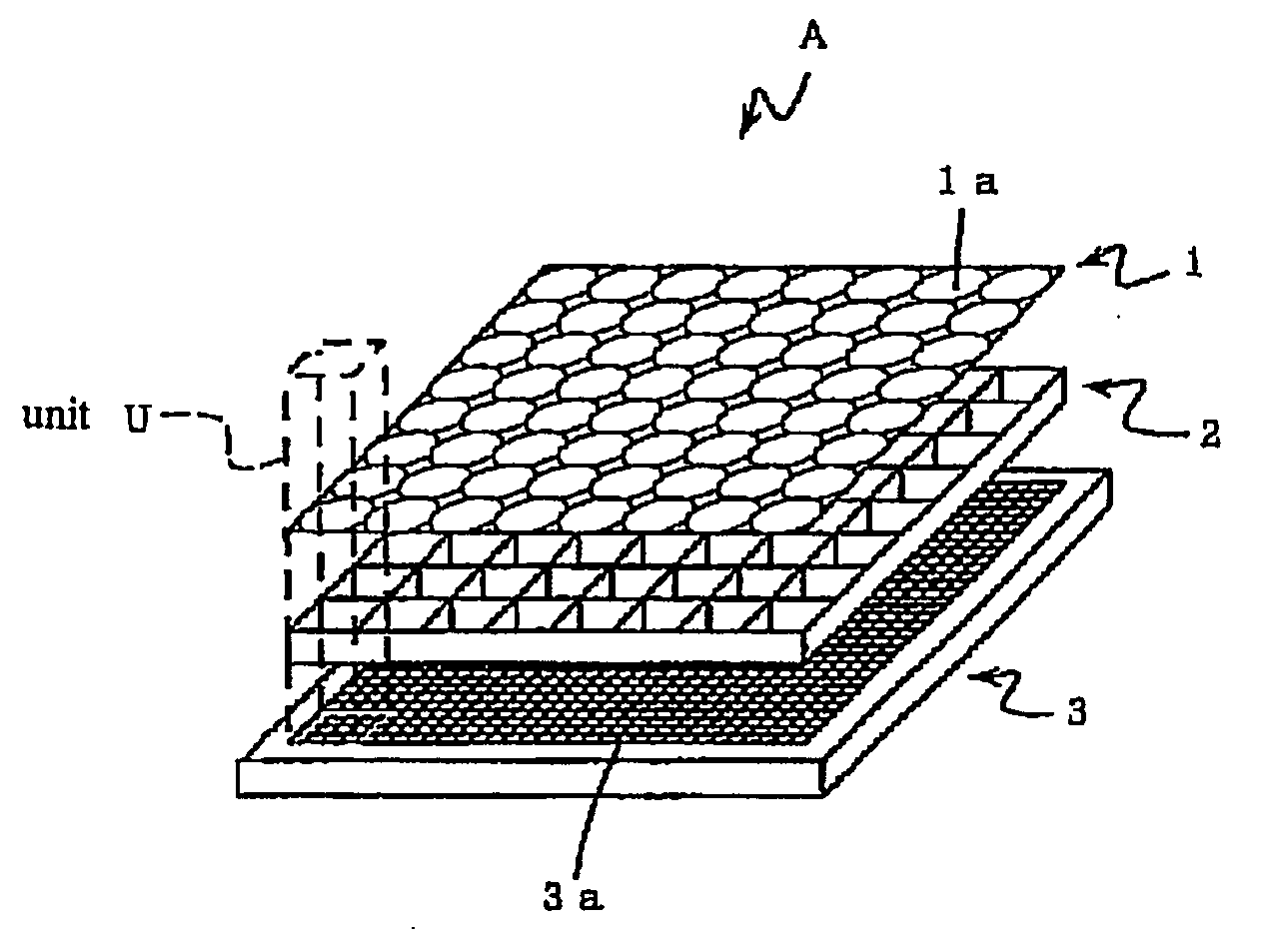
[0039] As shown in FIG. 1, the image input apparatus (A) is comprised of a micro-lens array (1) arraying a plurality of micro-lenses (1a) in a grid-like pattern, a light detecting element (3) forming planimetrically a plurality of light detecting cells (3a), and a grid-shaped partition wall (2) arranged between micro-lens array (1) and light detecting element (3). Here, as indicated by the rectangular column of dotted line in the FIG. 1, micro-lens (1a) forms a signal-processing...


PUM


Abstract

An image input apparatus which reconfigures a single reconfigured image from a plurality of low-resolution, object reduced images formed in a specified region on the light detecting element by the micro-lens array, wherein a high-resolution, single reconfigured image can be obtained even if the distance between the subject and the micro-lens array is long (infinitely long, for example), and further a reconfigured image can be realized in colors. The image input apparatus is characterized in that the relative distance between a micro-lens (1a) and light detecting cells (3a) in a specified region, where object reduced images corresponding to the micro-lens (1a) are formed, is different in each micro-lenses (1a). In addition, the light detecting cells (3a) are divided into a plurality of regions, and color filters (primary color filter, or complementary color filter, for example) are disposed in each of the divided regions.

Description

BACKGROUND OF THE INVENTION [0001] 1. Field of the Invention [0002] The present invention relates to an image input apparatus which can reconfigure a single, high-resolution object image from a plurality of low-resolution, object reduced images obtained by a plurality of micro-lens, wherein a high-resolution image of the object image can be obtained even if the imaging distance is long (infinitely long, for example), and the object image can be realized in colors. [0003] 2. Description of the Related Art [0004] With the arrival of the information society accompanying with the development of the media for communication, image input devices such as digital cameras and video cameras for obtaining the image by a single optical system facing the subject, have already been in use as the image reader which allows effectively obtaining various kinds of high-quality image information. [0005] However, in these days, the image reader imitating the compound-eye found in insects has being develo...

Claims


Application Information

Patent Timeline
IPC IPC(8): H04N5/225H01L27/00G02B3/00H01L27/14H04N5/335H04N5/369H04N9/04H04N9/07
CPCG02B3/0056H04N5/2253H04N5/2254H04N5/23229H04N9/045H04N23/54H04N23/80H04N25/136H04N25/134
Inventor MIYATAKE, SHIGEHIROTANIDA, JUNYAMADA, KENJI
Owner KONICA MINOLTA INC
Learn More