Loop connection detecting method and device

Inactive Publication Date: 2006-04-06
FUJITSU LTD
View PDF3 Cites 21 Cited by
  • Summary
  • Abstract
  • Description
  • Claims
  • Application Information

AI Technical Summary

Benefits of technology

[0035]FIGS. 2A and 2B are diagrams illustrating an effect of a loop con

Problems solved by technology

This is a problem in the conventio

Method used


Image

  • Loop connection detecting method and device
  • Loop connection detecting method and device
  • Loop connection detecting method and device

Examples


operational embodiment (

2)

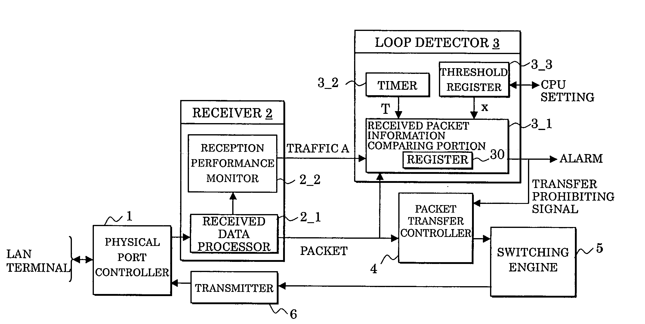
[0055] The embodiment (2) deals with the case where the register 30 in the received packet information comparing portion 3_1 is composed of five registers 30_1-30_5 (not shown). Therefore, only the steps with the reference numerals to which “0” is added are different from the steps in the operational embodiment (1) shown in FIG. 4.

[0056] Namely, at the initial setting (at step S120), the traffic A, pieces of packet information B1-B5 held in the five registers 30_1-30_5, same packet reception frequencies C1-C5 with respect to the registers 30_1-30_5, the packet information holding number D, the acquired packet information E, and the measurement time T of the timer 3_2 are respectively cleared.

[0057] Firstly, in the same way as the above-mentioned embodiment (1), when the measurement of the timer 3_2 is started (at step S13), the packet reception (at step S14) and the acquisition of the traffic A [%] (at step S15) are performed. The traffic A is compared with the threshold “m” (at...


PUM


Abstract

In an access portion of a LAN, traffic of a received packet is detected, whether or not the traffic exceeds a predetermined threshold is determined, packet information specific to the received packet is acquired when it is determined that the traffic exceeds the threshold, and an occurrence of a loop connection,is determined when the packet information acquired is compared with packet information previously held and a number of conformity thereof amounts to a predetermined number within a predetermined time.

Description

BACKGROUND OF THE INVENTION [0001] 1. Field of the Invention [0002] The present invention relates to a loop connection detecting method and device, and in particular to a loop connection detecting method and device which detect a loop on a network to halt a packet transfer. [0003] 2. Description of the Related Art [0004]FIG. 6 shows an arrangement of a generally-known LAN (Local Area Network), which is composed of a core portion 10 and access portions ACC1-ACC4. It is to be noted that the access portions ACC1-ACC4 are respectively composed of hub switches 20 (collectively represented), which are connected to terminals (not shown). As means for improving availability of this LAN, LAN switches 10_1-10_4 provided in the core portion 10 are connected e.g. as shown in FIG. 6; the switches 10_1 and 10_2, the switches 10_2 and 10_4, the switches 10_4 and 10_3, and the switches 10_3 and 10_1 are respectively interconnected. This connection makes paths between the LAN switches redundant. In ...

Claims


Application Information

Patent Timeline
IPC IPC(8): H04J1/16
CPCH04L12/2854
Inventor FUKUI, SATOSHISHIMAMOTO, KAORU
Owner FUJITSU LTD
Why Eureka
Try Eureka