
Method for evaluating signal transmission quality

a signal transmission and quality technology, applied in the field of signal transmission quality, can solve the problems of inability of the receiving end to know what the input data is and whether the input data is correct, and inability to effectively optimize the adjustmen

Active Publication Date: 2006-04-06
REALTEK SEMICON CORP
View PDF16 Cites 20 Cited by
  • Summary
  • Abstract
  • Description
  • Claims
  • Application Information

AI Technical Summary

Benefits of technology

[0005] An object of the present invention is to provide a method to evaluate signal transmission quality.
[0006] An object of the present invention is to provide a method to adjust the parameter of the circuit at the receiving end according to a result of evaluating signal transmission quality.
[0007] According to the present invention, a method for assessing the signal transmission quality comprises: receiving a digital signal at a receiving end from a transmitting end via a channel; counting a number of transitions of the digital

Problems solved by technology

There are various situations (e.g., different transmission line lengths, high and low frequencies, and so on) during the process of signal transmission so that it is inappropriate for the circuits at the receiving end using the same setting to receive data under different situations.
Moreover, because the transmitted data are image data, the receiving end is not able to know what the input data are and whether the input data are correct.
This method, however, can't effectively make the optimized adjustment in accordance with the present situation.

Method used


Image

  • Method for evaluating signal transmission quality
  • Method for evaluating signal transmission quality
  • Method for evaluating signal transmission quality

Examples


Embodiment Construction

[0014] The present invention will be exemplified with but not limited to a DVI interface below.

[0015] Because there are various situations in a channel such as the impedance of a transmitting end, the length of a transmission line, the transmission speed, and so on, it is difficult for a receiving end to use the same setting for receiving signals in various situations. The present invention makes use of a digital control signal sent via the channel to the receiving end to assess the quality of the digital control signal and adjust the setting of the circuit at the receiving end based on the assessment result.

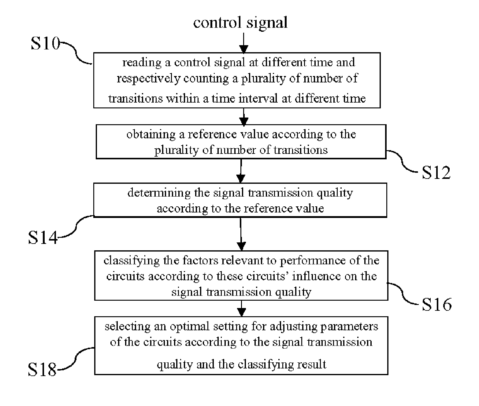
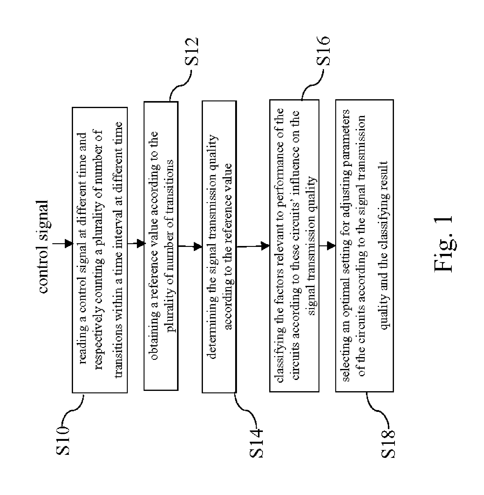
[0016]FIG. 1 shows an embodiment of the present invention. As shown in FIG. 1, a method for evaluating signal transmission quality comprises the following steps:

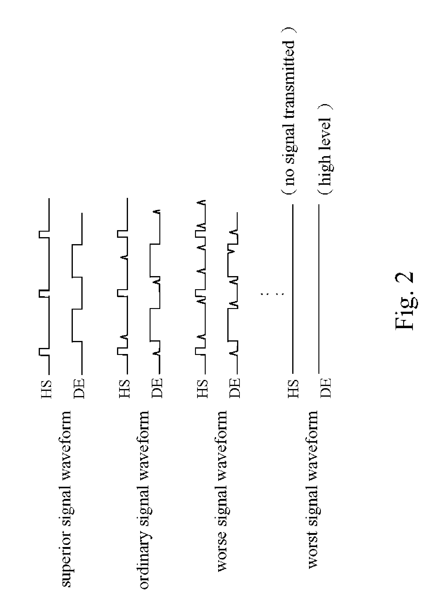
[0017] Step S10: reading a control signal with a format at different time, in which the control signal such as a HS (horizontal synchronization) signal, a VS (vertical synchronization) signal, a DE (data enable) signa...


PUM


Abstract

A method to assess signal transmission quality and the adjust method thereof are proposed. First, different time points of a control signal at a receiving end are acquired and the number of signal transition in a predetermined time interval is counted. Next, the number of signal transition is recorded and compared to obtain a comparison result. The quality of control signal is then determined based on the comparison result. Besides, the parameter setting of the receiving end is adjusted according to the quality of the control signal received by the receiving end to get a better performance setting.

Description

FIELD OF THE INVENTION [0001] The present invention relates to signal transmission quality and, more particularly, to a method for evaluating signal transmission quality. BACKGROUND OF THE INVENTION [0002] The DVI (Digital Visual Interface) standard is a standard for a graphics card communicating with a monitor. The DVI standard adopts transmission minimized differential signaling (TMDS) for data transmission between the graphics card and the monitor. Digital signals (including control and data information) generated by a graphics card are sent from a transmitting end through a TMDS channel (including four data lines: three data signals (RGB) and a clock signal) to a receiving end. After decoding the digital signals, the decoded signals are transferred to a digital display circuit for displaying an image on the monitor. [0003] There are various situations (e.g., different transmission line lengths, high and low frequencies, and so on) during the process of signal transmission so tha...

Claims


Application Information

Patent Timeline
IPC IPC(8): G10L21/00H04N7/52
CPCH04N17/004
Inventor CHOU, YU-PINLU, CHAO-HSINTUNG, HSU-JUNG
Owner REALTEK SEMICON CORP
Learn More