Mechanical pan, tilt and zoom in a webcam

Active Publication Date: 2006-04-06
LOGITECH EURO SA
28 Cites 49 Cited by

AI-Extracted Technical Summary

Problems solved by technology

However, most conventional cameras used for instant messaging (often webcams) do not move automatically to track a user's face.
First, the quality of such optically processing image data is significantly degraded.
Thus if the user were to move enough to go ...

Benefits of technology

[0014] In one embodiment, the video is supplied to an instant messaging application. The use of a standard bus (e.g., USB) and the offloading of the face tracking to the webcam and driver allows easy use by the instant messaging application.
[0015] In one embodiment, a machine vision algorithm localizes the user's face in the webcam's current field of view. The webcam is moved based on positive localization of the face and its facial features. In one embodiment of the present invention, an algorithm is used to compare this location of the user's face to the current field of view of the webc...

Abstract

A system and method for mechanically panning, tilting, and/or zooming a webcam to track a user's face. In one embodiment, such movement is controlled by kernel software in a host to which the webcam sends video data. In this way, a driver in the host kernel handles the face tracking, transparent to the application programs that would access the video. In an alternate embodiment, such movement is controlled by firmware in the webcam itself. The video and control signals are sent over the same standard cable, such as a USB bus. In one embodiment, the video is supplied to an instant messaging application. The use of a standard bus (e.g., USB) and the offloading of the face tracking to the webcam and driver allows easy use by the instant messaging application.

Application Domain

Television system detailsTwo-way working systems +1

Technology Topic

Message passingNetwork camera +5

Image

  • Mechanical pan, tilt and zoom in a webcam
  • Mechanical pan, tilt and zoom in a webcam
  • Mechanical pan, tilt and zoom in a webcam

Examples

  • Experimental program(1)

Example

[0025] The figures (or drawings) depict a preferred embodiment of the present invention for purposes of illustration only. It is noted that similar or like reference numbers in the figures may indicate similar or like functionality. One of skill in the art will readily recognize from the following discussion that alternative embodiments of the structures and methods disclosed herein may be employed without departing from the principles of the invention(s) herein.
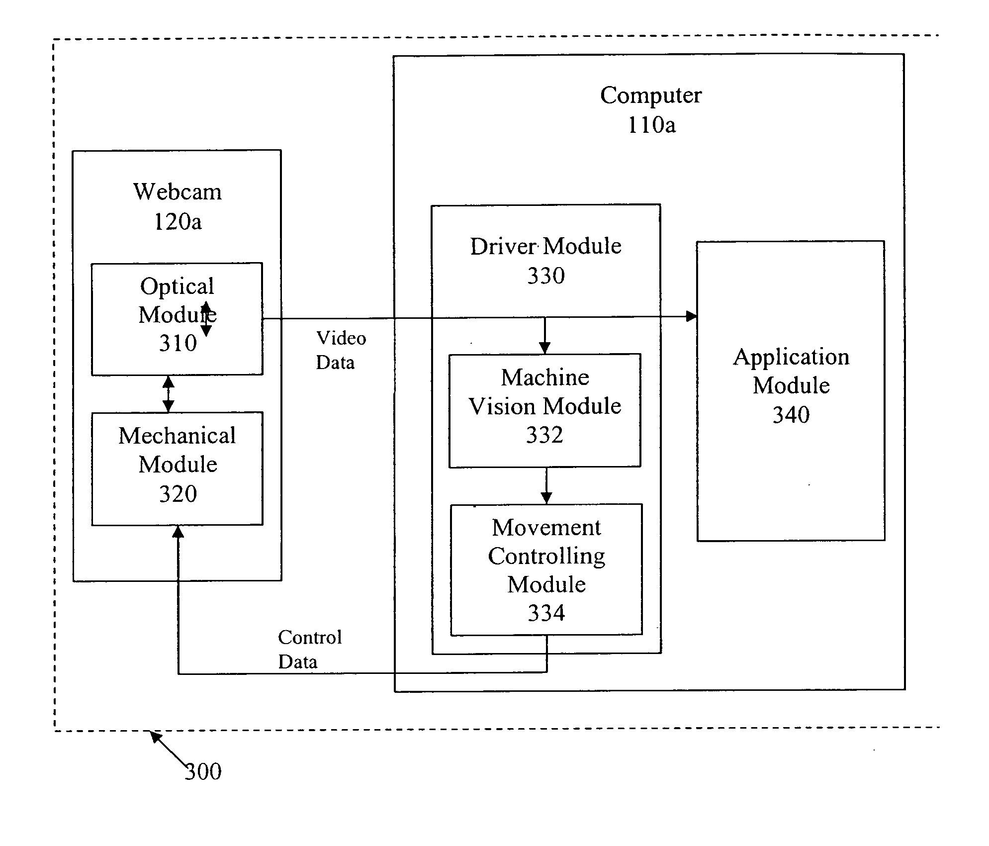
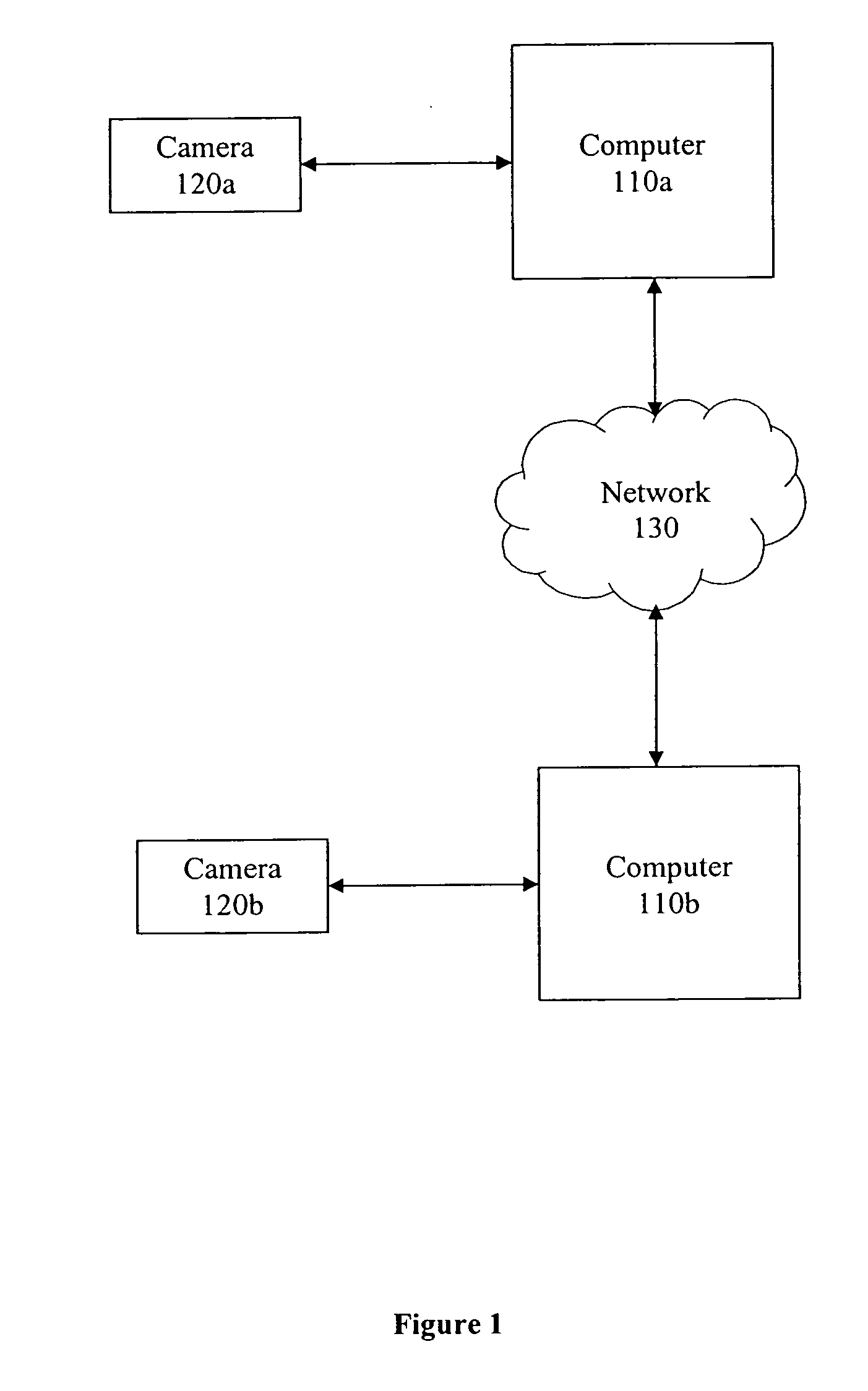
[0026]FIG. 1 is a block diagram of one embodiment of a system 100 for video communication. System 100 comprises computer systems 110a and 110b, webcams 120a and 120b, and network 130. A user using computer 110a and webcam 120a can communicate with a user using computer 110b and webcam 120b over the network 130.
[0027] The computer 110a or 110b could be any host which is able to communicate with the webcam 120a or 120b, and/or the network 130. Thus the computer 110 or 110b could be a personal computer (desktop or laptop), a handheld computer or organizer (such as a Personal Digital Assistant (PDA)), a cellular phone, an embedded automotive solution capable of interfacing with webcam and/or network, and so on. In one embodiment, the computers 110a and 110b are part of conventional computer systems, that may each include a storage device, a network services connection, and conventional input/output devices such as, a display, a mouse, a printer, and/or a keyboard, that may couple to a computer system. The computer 110a or 110b also includes a conventional operating system (such as MS Windows, Mac OSX operating system, etc.), input/output device, and network services software. In addition, in one embodiment, the computer 110a or 110b includes IM software, such as ICQ from ICQ, Inc., America OnLine Instant Messenger (AIM) from America Online, Inc. (Dulles, Va.), MSN® Messenger from Microsoft Corporation (Redmond, Wash.), and Yahoo!® Instant Messenger from Yahoo! Inc. (Sunnyvale, Calif.).
[0028] The network service connection includes those hardware and software components that allow for connecting to a conventional network service. For example, the network service connection may include a connection to a telecommunications line (e.g., a dial-up, digital subscriber line (“DSL”), a T1, or a T3 communication line). The host computer, the storage device, and the network services connection, may be available from, for example, IBM Corporation (Armonk, N.Y.), Sun Microsystems, Inc. (Palo Alto, Calif.), or Hewlett-Packard, Inc. (Palo Alto, Calif.).
[0029] Webcams 120a and 120b are connected to the computers 110a and 110b respectively. Webcams 120a and 120b can be any cameras connectable to computers 110a and 110b. In one embodiment, webcams 120a and/or 120b are QuickCam® cameras from Logitech, Inc. (Fremont, Calif.).
[0030] The network 130 can be any network, such as a Wide Area Network (WAN) or a Local Area Network (LAN), or any other network. A WAN may include the Internet, the Internet 2, and the like. A LAN may include an Intranet, which may be a network based on, for example, TCP/IP belonging to an organization accessible only by the organization's members, employees, or others with authorization. A LAN may also be a network such as, for example, Netware™ from Novell Corporation (Provo, Utah) or Windows NT from Microsoft Corporation (Redmond, Wash.). The network 120 may also include commercially available subscription-based services such as, for example, AOL from America Online, Inc. (Dulles, Va.) or MSN from Microsoft Corporation (Redmond, Wash.).
[0031]FIGS. 2A, 2B and 2C provide an example of the functioning of an embodiment of the present invention. FIGS. 2A, 2B and 2C illustrate a field of view of the webcam 120a (200 in FIGS. 2A and 2B, and 202 in FIG. 2C), the head of a user/speaker 210, and a stationary background feature 220, denoted by two vertical lines.
[0032] In FIG. 2A, the speaker's head 210 is in the center of the field of view 200 of the webcam 120a. It can be seen from FIG. 2A that the stationary background feature 220 is behind the speaker's head at this time, and is thus also in the center of the field of view 200 of the webcam 120a.
[0033] Let us assume that the speaker then moves to the left. FIG. 2B illustrates that the speaker's head 210 moves to the left of the field of view 200 of the webcam 120a. The stationary background feature 220 is still at the center of the field of view 200 of the webcam 120a.
[0034]FIG. 2C illustrates how a system in accordance with an embodiment of the present invention will accommodate this movement by the speaker. In one embodiment, the system detects that the speaker's head 210 is too close to the edge of the camera's current field of view 200. The lens of the camera then moves and changes its field of view, so that the speaker's head 200 is in the center of its new field of view 202. It can be seen that the background feature 220, being stationary, is no longer in the center of the new field of view 202.
[0035] It is to be noted that since the webcam 120a can modify its field of view to accommodate movements by the speaker, the effective field of view of the webcam 120a is significantly larger than that of conventional cameras. It is also to be noted that in the above example, the speaker moved from right to left. In one embodiment, the same accommodation by movement of the lens would take place even if the speaker moved in other directions (such as left to right, up to down, down to up, or a combination of these). In one embodiment, the field of view is automatically adjusted (i.e. it zooms outs and zooms in when the speaker moves closer to the camera or further away from the camera respectively), so as to maintain the same size of the speaker's head in relation to the field of view of the camera. In one embodiment, the automatic adjustment of the field of view can be achieved by zooming the lens on the webcam. In another embodiment, the automatic adjustment of the field of view can be achieved using electronic zoom (on the webcam itself or on the host computer).
[0036]FIG. 3 is a block diagram of a system in accordance with an embodiment of the present invention. System 300 comprises the webcam 120a and the computer 110a.
[0037] The webcam 120a is comprised of an optical module 310 and a mechanical module 320. In one embodiment, the optical module 310 comprises of the lens, sensor, and firmware that allows video processing and compression. The mechanical module 320 includes the mechanics for moving the lens. In one embodiment, actuators are used for moving the lens. In one embodiment, the actuators cause the mechanical lens displacement it either direction through a gearbox that translates the actuator revolutions into webcam motion. In one embodiment, two actuators and two gearboxes are used, and each actuator controls one gearbox. Once the decision is made to move the lens mechanically, the webcam's firmware (software embedded in the webcam itself) is ordered to do so. The firmware sends signals to the actuators which in turn move the gearboxes, which in turn moves the webcam and/or its lens.
[0038] The software on the computer 110a includes a driver module 330 and an application module 340. The driver module 330a includes a Machine Vision Module 332, and a Decision Making Module 335. The Machine Vision Module 332 tracks the location of the face of the speaker within the field of view of the webcam 120a, and is further described below with reference to FIG. 5. Based on output from the Machine Vision Module 332, the Movement Controlling Module 334 decides whether, and how much, to move the camera. The Movement Controlling Module 334 is further described below with reference to FIG. 6. The application module 340 is the application that the user interacts with when using the webcam 120a.
[0039]FIG. 4 is a flowchart illustrating the functioning of system 300. Video data sent from the webcam 120a is received (step 410) by the computer 110a. The video data is then processed (step 420) to assess the position of the user's face in the frame. The machine vision module 332, which is described below with reference to FIG. 5, performs this processing.
[0040]FIG. 5 is a block diagram of a Machine Vision Module 332 in accordance with an embodiment of the present invention.
[0041] The Machine Vision Module 332 includes a face detector 510, a flesh sampler 515, a flesh tracker 520, and a motion detector 530. The face detector 510, the flesh tracker 520, and the motion detector 530, each use different parameters to determine where a user's face may be located within the frame captured by the camera. The outputs of these modules affect each other, and together they provide an estimate of where the user's face is within the camera's field of view.
[0042] The face detector 510 detects the presence of a face based on certain parameters expected to be common to all human faces. These parameters might include, for example, the existence of two eyes, a nose, and a mouth, with a certain spacing ratio between them.
[0043] The output of the face detector 510 is then fed to the flesh sampler 515. The flesh sampler selects a particularly smooth area from the “face” as determined by the face detector 510. For instance, this area may be an area from the forehead of the user. This area is then used as a sample of the user's flesh. Using a sample of the user's face eliminates differences in flesh tone across different users, as well as any differences in flesh tones due to the lighting in the user's environment. The output of the flesh sampler 515 is provided to the flesh tracker 520. The flesh tracker 520 then uses the sample of flesh sampler 515, and tracks the user's face by tracking the user's flesh as it moves.
[0044] The motion detector 530 detects motion. When the user moves his/her head, the motion detector 530 is able to identify that motion. The motion detector 530 also receives information from the face detector 510 and the flesh tracker 520. Thus these three modules work in conjunction to identify something that has the parameters of a human face, has flesh tones, and which is moving. Thus, the machine vision module 332 can “see” the user's face in the frame, relative to the field of view of the camera. In one embodiment, the output of the machine vision module is a rectangle within which the user's face is contained.
[0045] Referring again to FIG. 4, a decision is then made (step 430) regarding whether, and in which direction, the webcam lens should be moved. In one embodiment, the webcam lens is moved up-down, left-right, etc. by moving the webcam itself. In another embodiment, the webcam lens is moved without moving the housing of the webcam. In one embodiment, the decision to move the webcam lens (step 430) includes calculating the amount by which the lens should be moved. In another embodiment, the lens is moved by a predetermined amount in the specified direction. In one embodiment, the decision is made (step 430) by determining whether the user's face is outside of a threshold in the frame. FIG. 6 illustrates this in some detail.
[0046]FIG. 6 is a block diagram which illustrates how a decision is made about whether to move the lens of the webcam, how much to move it by, and the direction in which to move it, in accordance with an embodiment of the present invention.
[0047] Rectangle 610 represents the current field of view of the webcam 120a. Rectangles 630a, b, and c represent the position of the face of the user. In one embodiment, rectangles 630a, b, and c are provided by the machine vision module 332. Rectangle 620 represents a predetermined threshold relative to the current field of view 610 of the webcam 120a. An algorithm relating the position of the face of the user (i.e. 630a, b, or c) to the threshold 620 determines whether, how much, and in what direction to move the lens. For instance, in one embodiment, the algorithm is that the lens need not be moved as long as the center of the rectangle representing the user's face 630a, b, or c) is within the threshold rectangle 620. When the center of the rectangle representing the user's face 630a, b, or c is outside the threshold rectangle 620, the lens is to be moved until the user's face 630a, b, or c is once again inside the threshold rectangle.
[0048] It can be seen from FIG. 6 that using such an algorithm, no lens motion is needed when the user's head is in positions 630a and 630b. However, when the user's face is in position 630c, the lens needs to be moved both downwards and to the right.
[0049] Referring again to FIG. 4, it can be seen that if it is decided (step 430) that the camera should not be moved, the system continues to receive the video data (step 410) and process it (step 420). If it is decided that the webcam needs to be moved to track the face, the lens of the webcam is moved in the specified direction in the calculated or predetermined amount. The system continues to receive the video data (step 410) and process it (step 420).
[0050] It is to be noted that in an alternate embodiment, the machine vision module 332, and other related modules, are embedded in the webcam 120a itself, rather than being on the computer 110a. In one embodiment, the mechanical panning, tilting, and/or zooming of the camera is controlled by the webcam's firmware. In one embodiment, the machine vision module 332 and/or the movement controlling module 334 could be included in the camera itself, either in their entirety, or in part.
[0051]FIG. 7 illustrates the relationship between the webcam, host kernel layer (driver) and the application program. A webcam 700 includes a video sensor 702 and actuators 704 for motorized control of the pan, tilt and zoom of the video sensor. A USB interface both provides the video signal 712 to the host, and receives actuator control commands 714 from the host for controlling the actuators. This allows a standard bus to be used for controlling the webcam.
[0052] In the host, a kernel layer 710 includes a driver with a face tracking system 716. This monitors the video 712, and provides actuator control signals transparent to the application program 720. The video signal 712 is also provided to the application program 720. The solid line represents the video path with face tracking, the dotted line represents the video path without face tracking. In the example shown, the application program is an instant messaging program. The instant messaging program has a messaging window 722 and a video capture window 724 for displaying the video 712. A button icon may be displayed in the messaging window for activating the face tracking feature.
[0053] While particular embodiments and applications of the present invention have been illustrated and described, it is to be understood that the invention is not limited to the precise construction and components disclosed herein. For example, as mentioned above, the present invention can be used with other applications that pull video from a webcam, not just instant messaging. Various other modifications, changes, and variations which will be apparent to those skilled in the art may be made in the arrangement, operation and details of the method and apparatus of the present invention disclosed herein, without departing from the spirit and scope of the invention as defined in the following claims.

PUM

no PUM

Description & Claims & Application Information

We can also present the details of the Description, Claims and Application information to help users get a comprehensive understanding of the technical details of the patent, such as background art, summary of invention, brief description of drawings, description of embodiments, and other original content. On the other hand, users can also determine the specific scope of protection of the technology through the list of claims; as well as understand the changes in the life cycle of the technology with the presentation of the patent timeline. Login to view more.

Similar technology patents

Household appliance control method and device and mobile terminal

InactiveCN103605531Aeasy to operateeasy to use
Owner:GD MIDEA AIR-CONDITIONING EQUIP CO LTD +1

Multi-stage oral-fluid testing device

ActiveUS20160121322A1easy to use
Owner:PREMIER BIOTECH LLC

System and method of monitoring temperature

InactiveUS7140768B2less susceptible to tampereasy to use
Owner:COLD CHAIN TECH

Classification and recommendation of technical efficacy words

  • easy to use
Why Eureka
Try Eureka