Pick and place machine with improved component pick up inspection

a technology of component pick up and inspection, applied in the field of pick and place machines, can solve problems such as physical blockage of image acquisition, and achieve the effect of prompt and effective corrective actions

Inactive Publication Date: 2006-04-13
CYBEROPTICS
View PDF98 Cites 61 Cited by
  • Summary
  • Abstract
  • Description
  • Claims
  • Application Information

AI Technical Summary

Benefits of technology

[0009] Embodiments of the present invention improve upon component level inspection performed by pick and place machines. Such improvements include inspecting the pick operation in pick and place machines by collecting images of the pick event inside the machine and identifying errors as they happen. By detecting and displaying this information as it generated on the machine, the operator or machine can take prompt and effective corrective actions.

Problems solved by technology

Typical cameras found in pick and place machines, such as fiducial cameras, are downward looking and are physically blocked from acquiring an image of the pick position when the placement head is positioned above the pick position.

Method used


Image

  • Pick and place machine with improved component pick up inspection
  • Pick and place machine with improved component pick up inspection
  • Pick and place machine with improved component pick up inspection

Examples


Embodiment Construction

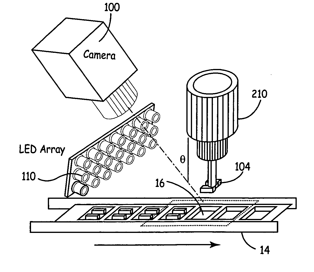
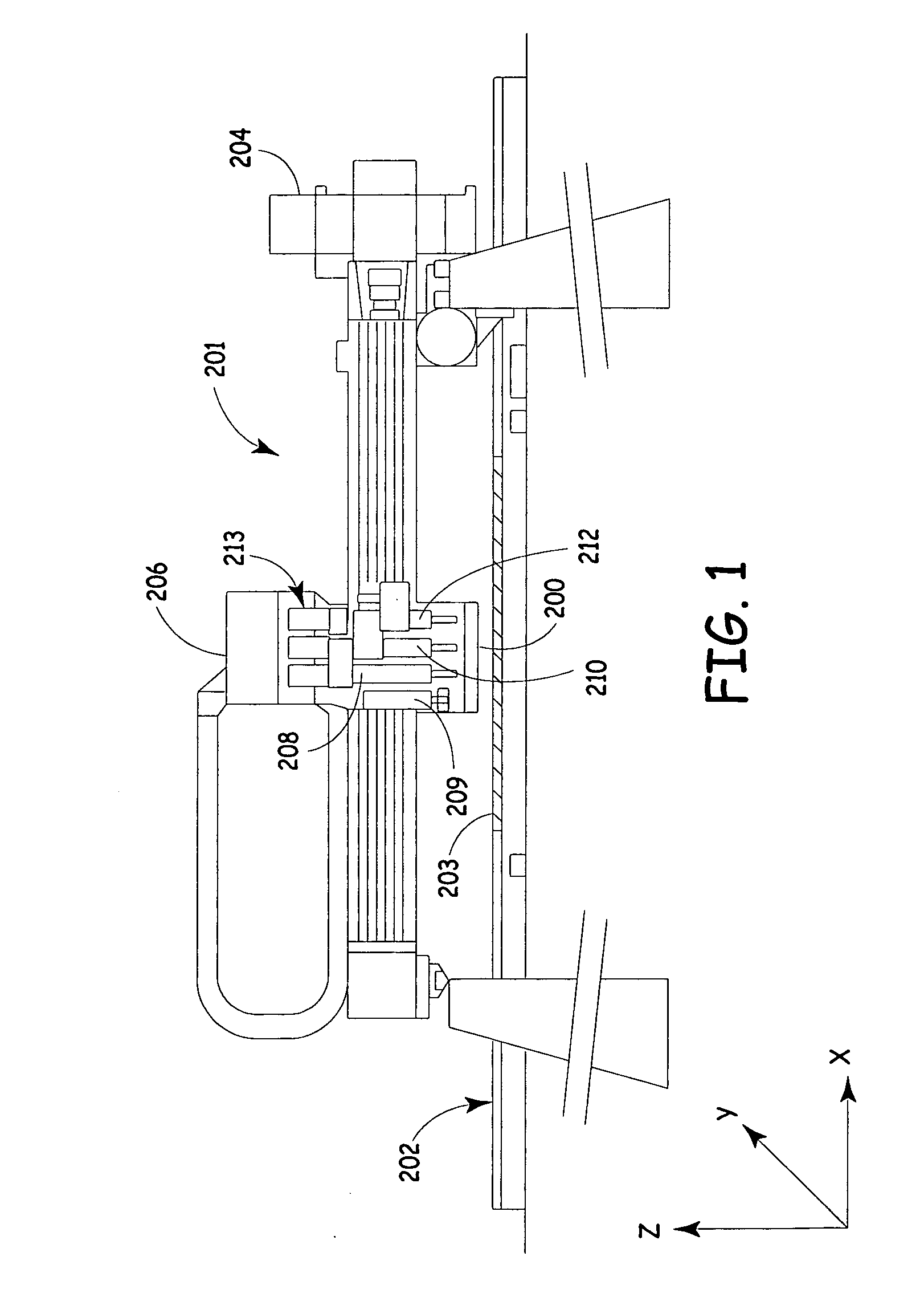
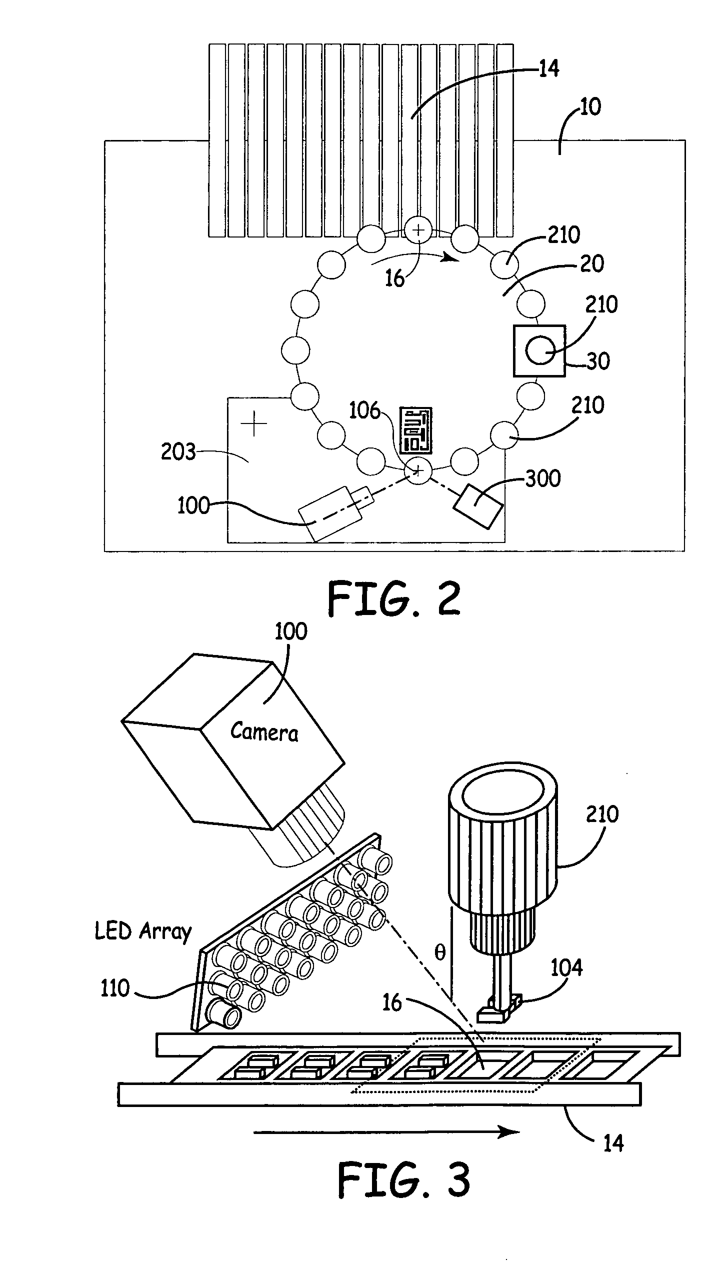
[0023]FIG. 1 is a diagrammatic view of an exemplary Cartesian pick and place machine 201 with which embodiments of the present invention are applicable. Pick and place machine 201 receives a workpiece, such as circuit board 203, via transport system or conveyor 202. A placement head 206 then obtains one or more electrical components to be mounted upon workpiece 203 from component feeders (not shown) and moves in x, y and z directions to place the component in the proper orientation at the proper location upon workpiece 203. Placement head 206 may include an alignment sensor 200 that may pass under components held by nozzles 208, 210, 212 as placement head 206 moves the component(s) from pickup locations to placement locations. Sensor 200 allows placement machine 201 to view undersides of components held by nozzles 208, 210, 212 such that component orientation and, to some degree, component inspection can be effected while the component is being moved from the component pick-up locat...


PUM

PropertyMeasurementUnit
polarityaaaaaaaaaa
heightaaaaaaaaaa
movementaaaaaaaaaa

Abstract

Embodiments of the present invention improve upon component level inspection performed by pick and place machines. Such improvements include inspecting the pick operation in pick and place machines by collecting images of the pick event inside the machine and identifying errors as they happen. By detecting and displaying this information as it generated on the machine, the operator or machine can take prompt and effective corrective actions.

Description

CROSS REFERENCE TO RELATED APPLICATIONS [0001] This application claims priority to U.S. provisional patent application Ser. No. 60 / 615,931, filed Oct. 5, 2004 entitled PICK AND PLACE MACHINE WITH IMPROVED COMPONENT PICK UP INSPECTION.COPYRIGHT RESERVATION [0002] A portion of the disclosure of this patent document contains material which is subject to copyright protection. The copyright owner has no objection to the facsimile reproduction by anyone of the patent document or the patent disclosure, as it appears in the Patent and Trademark Office patent files or records, but otherwise reserves all copyright rights whatsoever. BACKGROUND OF THE INVENTION [0003] Pick and place machines are generally used to manufacture electronic circuit boards. A blank printed circuit board is usually supplied to the pick and place machine, which then picks electronic components from component feeders, and places such components upon the board. The components are held upon the board temporarily by solde...

Claims


Application Information

Patent Timeline
Patent Type & Authority Applications(United States)
IPC IPC(8): B23P21/00
CPCH05K13/0413Y10T29/53178Y10T29/53191Y10T29/53087Y10T29/53039Y10T29/53091H05K13/0812B23P21/00H05K13/04
Inventor CASE, STEVEN K.HAUGEN, PAUL R.DUQUETTE, DAVID W.MADSEN, DAVID D.FISHBAINE, DAVIDFISHER, LANCE K.BADAR, TIMOTHY G.MANICKAM, SWAMINATHAN
Owner CYBEROPTICS
Why Eureka
Try Eureka