
Method for operating a gas turbine installation, and gas turbine installation

Inactive Publication Date: 2006-04-13
ALSTOM TECH LTD
View PDF6 Cites 7 Cited by
  • Summary
  • Abstract
  • Description
  • Claims
  • Application Information

AI Technical Summary

Benefits of technology

[0024] The liquid sensors on the compressor wall and/or the wall of the cooling air system may be positioned flush with the wall surface. They are secured either permanently or releasably by screw connection or flange connection, which allows the liquid sensor to

Problems solved by technology

Particular difficulties arise when using the “wet” operation of a compressor from the fact that the drops in the compressor on the one hand may strike blades and vanes and other surfaces at a high velocity and on the other hand lead to the formation of films of water on the blades and vanes and on the casing.
(II) water can penetrate into cooling air lines and other components of the cooling air system and have an adverse effect on the turbine cooling,
(IV) the impinging water drops may erode the blades and vanes and other structure parts and lead to increased corrosion through film formation.
However, the measurement devices which have hitherto been installed in commercially available gas turbine installations are unsuitable for this purpose.
Reliable determination of the presence of water in the compressor, the determination of the extent of the wet region and / or the drop size spectrum in the compressor is not therefore currently possible in installations of this type.

Method used


Image

  • Method for operating a gas turbine installation, and gas turbine installation
  • Method for operating a gas turbine installation, and gas turbine installation

Examples


Embodiment Construction

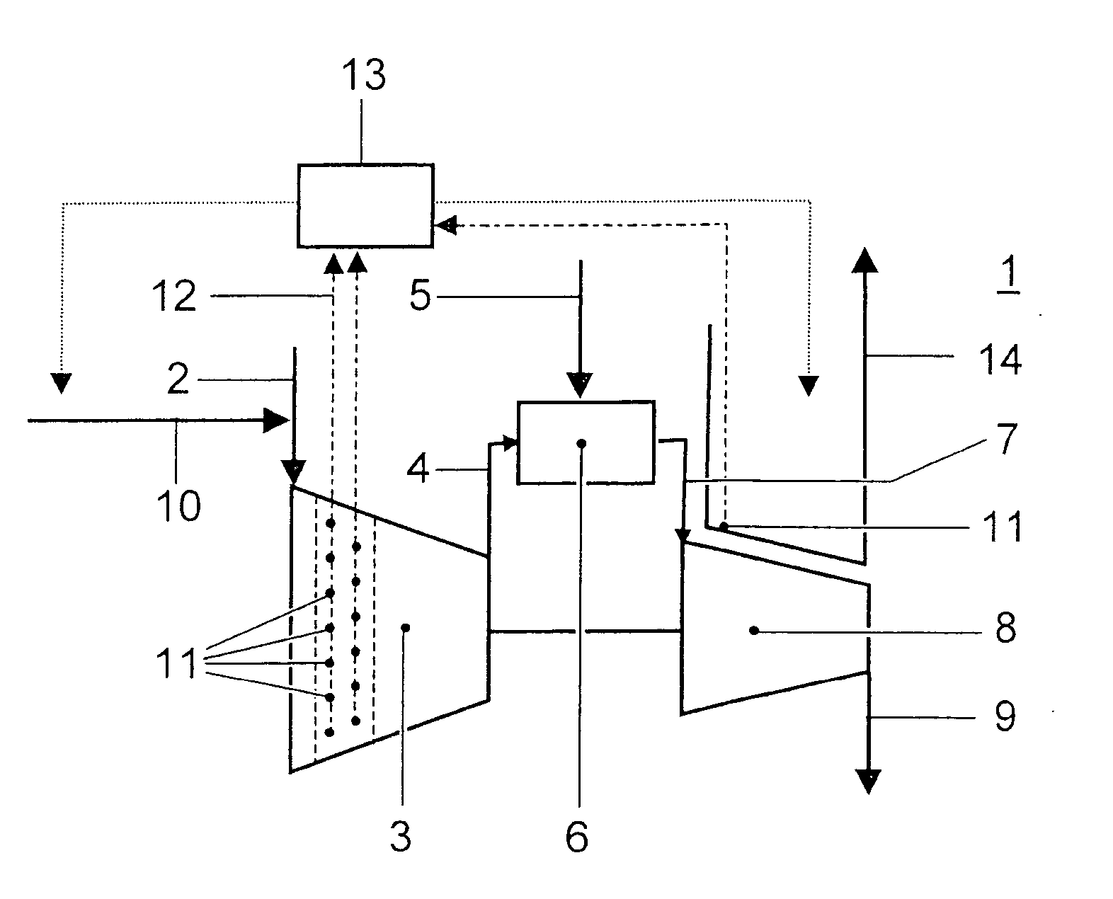
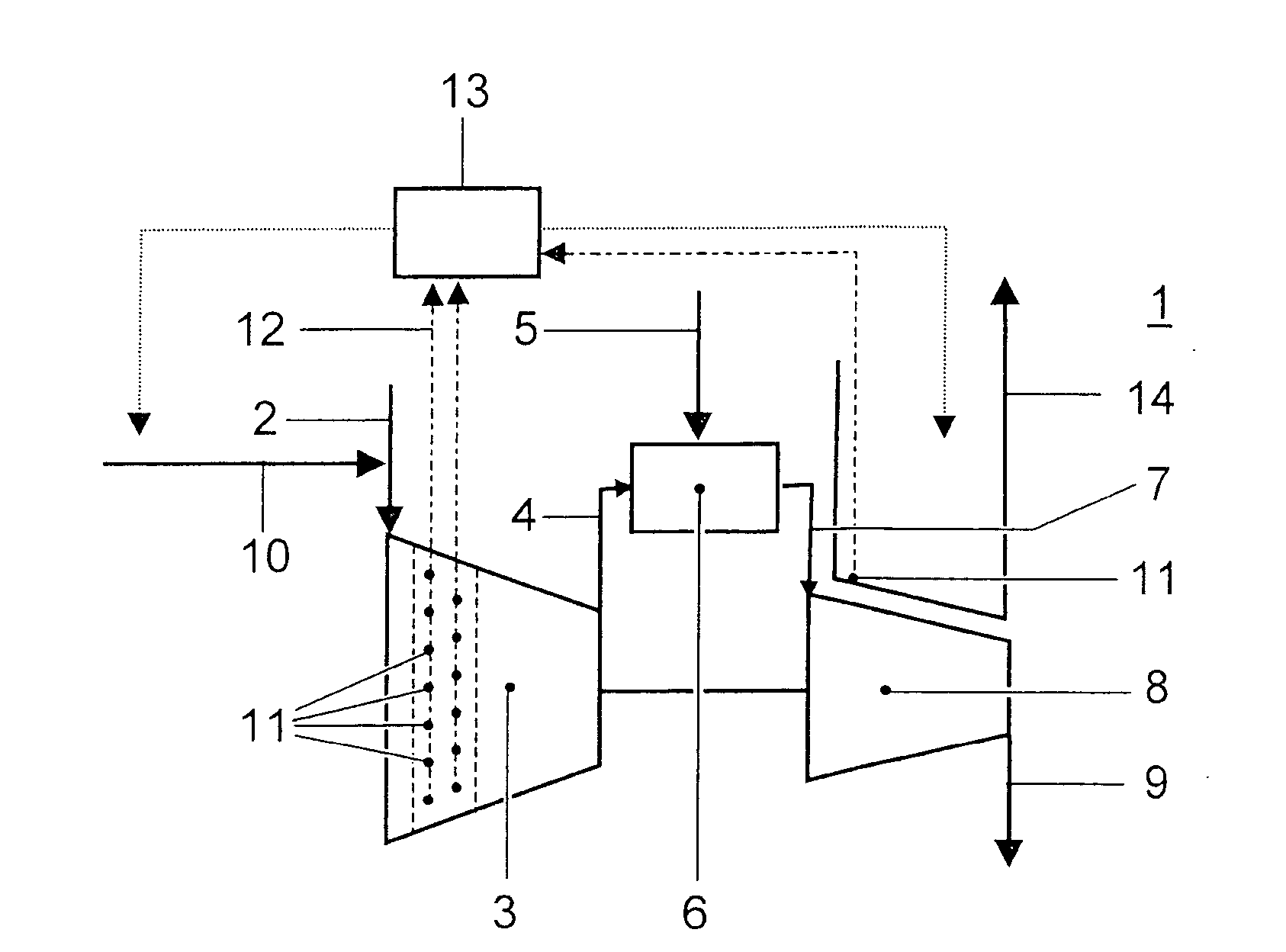
[0026] The only FIGURE illustrates a gas turbine installation 1. Air 2 is sucked in by a compressor 3. The compressed air 4 is burnt together with fuel 5 in a combustion chamber 6 to generate hot gases 7. Then, the hot gases 7 are passed into a turbine 8 which drives a generator (not shown) for generating electrical energy. The exhaust gases 9 which are formed can be used in a heat recovery scheme generator or in some other way. To increase the power, water 10 is injected into the compressor 3. As illustrated in the only FIGURE, it may be injected into the intake air 2 or also into certain stages of the compressor 3. In this way, a two-phase flow comprising a gaseous phase and a liquid phase is formed in a defined region of the compressor 3. As soon as the injected water 10 has evaporated, the two-phase flow is converted back into a single-phase flow comprising only a gas phase. Furthermore, the hot components of the gas turbine installation 1 are cooled by cooling air 14 which flow...


PUM


Abstract

A method for operating a gas turbine installation (1) includes sucking in a gaseous medium (2) by the compressor (3) and compressed in the compressor space, a liquid medium (10) being injected into the gaseous medium (2), so that a two-phase flow comprising a gaseous phase and a liquid phase is formed at least in a subregion of the compressor (3). The gaseous medium (2) is then burnt with fuel (5) in a combustion chamber (6) to form hot gases (7), and the hot gases (7) are expanded in a turbine (8), the hot components of the gas turbine installation (1) being cooled by cooling air (14) of a cooling air system. A measurement is carried out to determine whether a liquid phase is present in a region of the compressor (3) and / or of the cooling air system.

Description

[0001] This application is a Continuation of, and claims priority under 35 U.S.C. § 120 to, International application no. PCT / CH02 / 00651, filed 2 Dec. 2002, and claims priority to Swiss application no. 2002 1010 / 02, filed 13 Jun. 2002, the entireties of both of which are incorporated by reference herein.BACKGROUND OF THE INVENTION [0002] 1. Field of the Invention [0003] The present invention relates to a method for operating a gas turbine installation, and to a gas turbine installation. [0004] 2. Brief Description of the Related Art [0005] It is known from the prior art that the mass flow of the compressor can be cooled to increase the power of gas turbines. Cooling of the mass flow of air which is taken up by the gas turbine leads to an increased power output from the turbomachine. The reasons for this are firstly the increased mass flow of air resulting from the cooling and also the reduction in the power consumption of a compressor device at lower inlet temperatures. In principle...

Claims


Application Information

Patent Timeline
IPC IPC(8): F02C3/30F01K21/04F02C7/143F02C7/00F02C7/18F04D29/58
CPCF01K21/047F02C3/30F02C7/1435F04D29/5846
Inventor HAERTEL, CARLOS JIMENEZSAVIC, SASHAZINN, HANSPETER
Owner ALSTOM TECH LTD
Learn More