
Latch needle

Inactive Publication Date: 2006-04-13
GROZ BECKERT KG
View PDF12 Cites 4 Cited by
  • Summary
  • Abstract
  • Description
  • Claims
  • Application Information

AI Technical Summary

Benefits of technology

[0010] The latch needle according to the invention has a sawslot which widens toward the needle back, preferably relative to the longitudinal needle direction and, if needed, also widens in the transverse direction. A latch spring is arranged in the enlarged region of the sawslot. Thus, the respective spring-supporting pockets are open toward the needle back. Therefore, the latch spring may first simply be inserted into the sawslot at the needle back and may then be secured, for example, by an embossing step. A bending of the latch spring during insertion, as described, for example in DE-AS 1,113,537, is thus not necessary. The latch needle may thus be made with high precision with narrow tolerances. The new latch needle configuration thus has significant advantages concerning manufacturing technology.
[0013] Conventional latch springs may occasionally slip or entirely fall out of the latch needle. Should this happen, an orderly functioning of the latch needle is, in all probability, no longer possible. It has been found that the latch needle according to the invention, having a latch spring secured at the needle-back side, is substantially less sensitive as concerns a loss or misadjustment of the latch spring. The latch needles according to the invention permit very high knitting speeds with a high reliability.
[0016] Further, a shortening of the sawslot in the region of the hook at the needle breast may lead to a stiffening of the shank, thus increasing the stability of the latch needle in the region of the sawslot. In addition, the guidance of the latch in the sawslot may be improved, whereby lesser requirements can be set for the bearing arrangement of the latch. Such a guidance may be formed, for example, by pins or half-pins pressed out of the lateral slot flanks.

Problems solved by technology

Independently therefrom, dirt accumulating in the sawslot may adversely affect the operation.
Further, the latch spring is only moderately secured in the spring-supporting pockets in the depth of the sawslot.
The latch spring may slip and / or may become lost, and, as a result, the needle does no longer operate correctly.

Method used


Image

  • Latch needle
  • Latch needle
  • Latch needle

Examples


Embodiment Construction

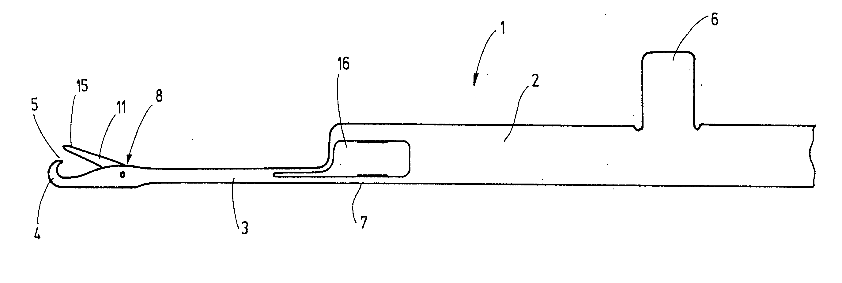
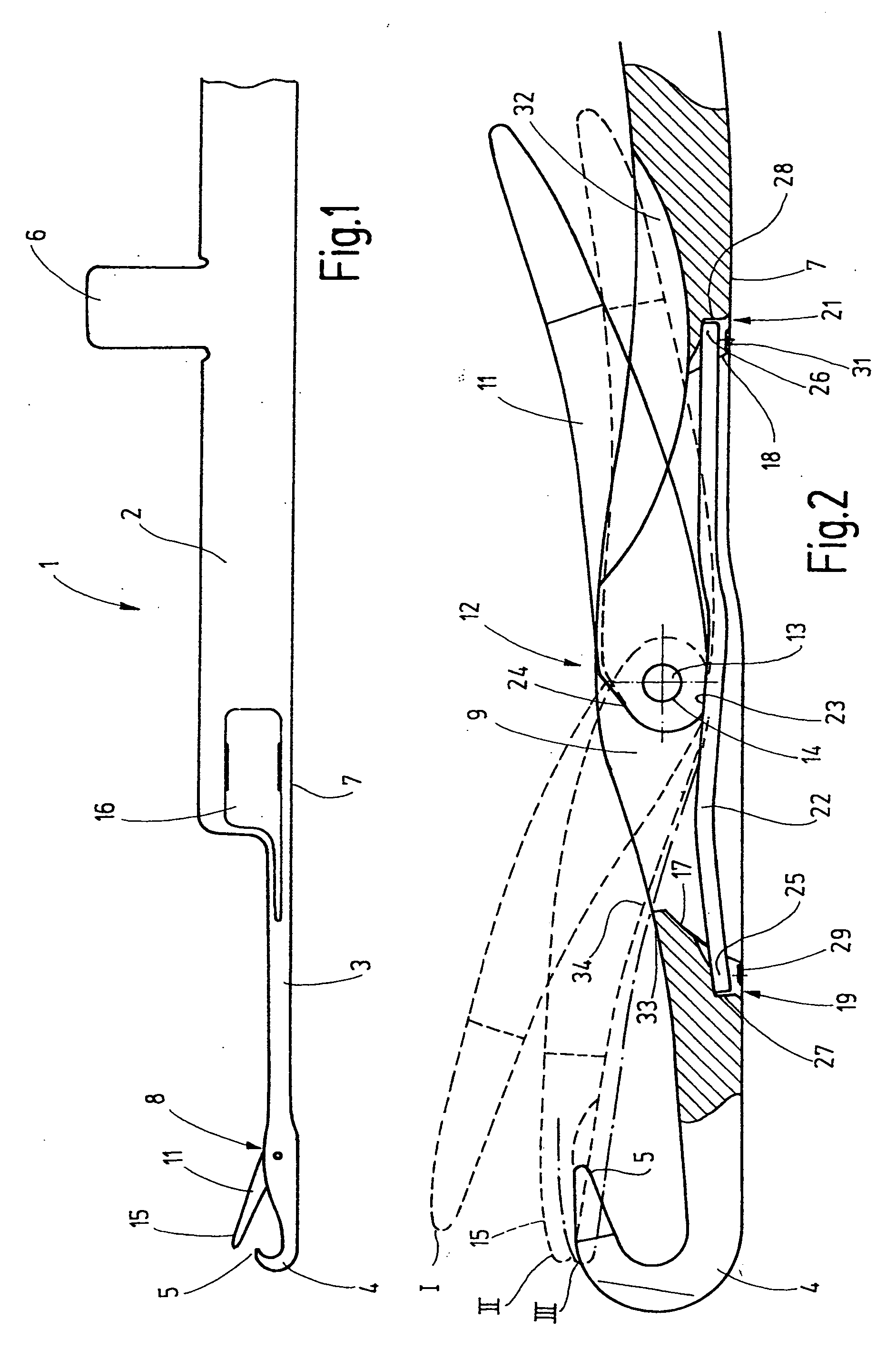
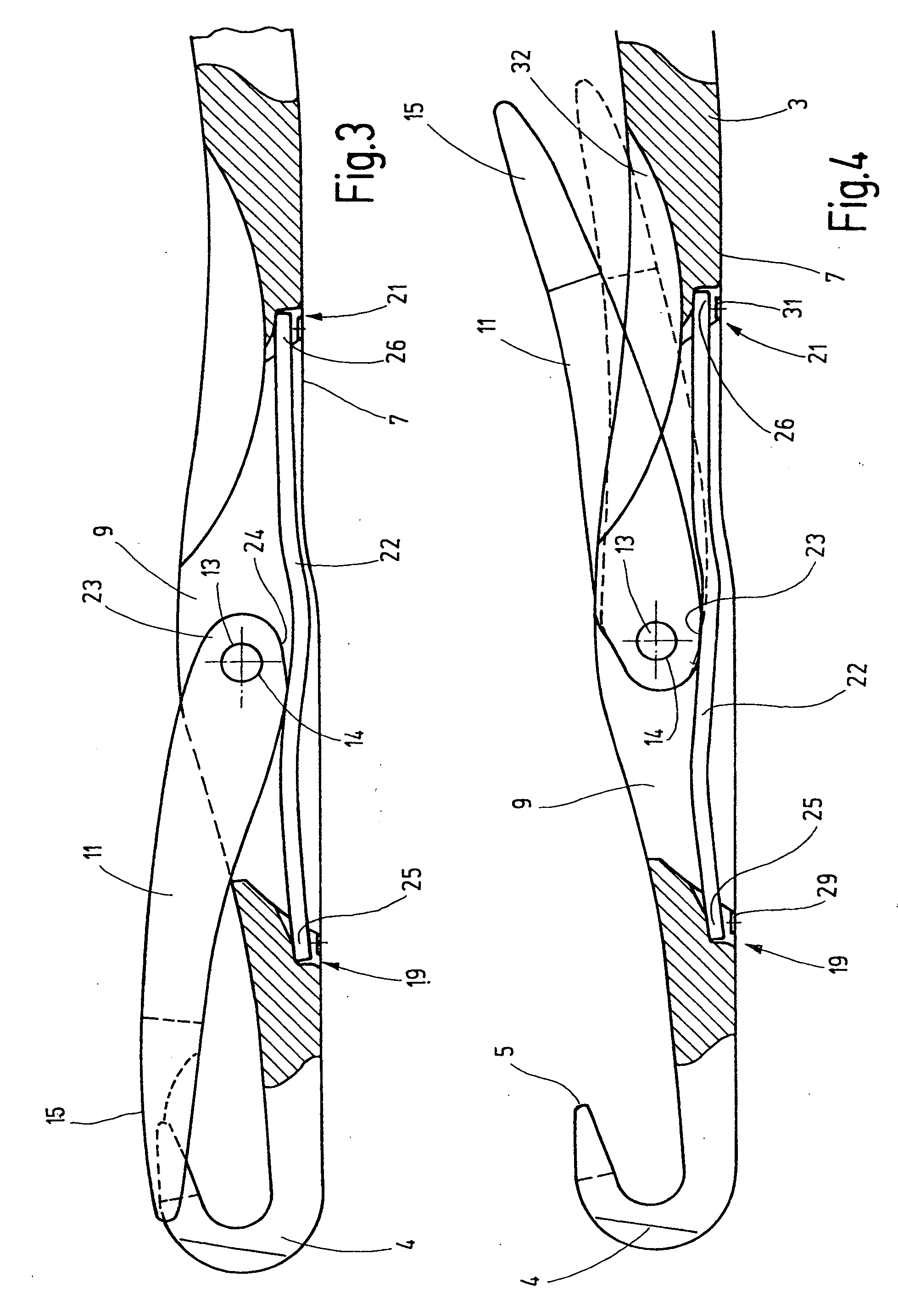
[0026]FIG. 1 illustrates a latch needle 1 which finds application primarily as a machine knitting needle or, in a similar configuration, as a stitch needle or the like. The latch needle 1 has a base body 2 which is flanked by two flat sides and from which a shank 3 extends. At its free end the shank 3 carries a hook 4, whose tip 5 is oriented toward the base body 2. In FIG. 2, the lower narrow side of the base body 2 and the shank 3, situated remote from the hook 4 of the latch needle 1 and its butt 6, constitutes the needle back 7. In FIG. 1, the upper narrow side of the shank 3 constitutes, at least in the immediate vicinity of the hook 4, a needle breast 8. In the region of the needle breast 8 the shank 3 is provided with a sawslot 9 visible in the sectional FIG. 2. The sawslot 9 serves for receiving one end of a latch 11, which is pivotally supported in a bearing device 12. The bearing device 12 is formed by a bearing means 13, such as a bearing pin which passes through a latch ...


PUM


Abstract

The starting point of a new concept in a latch needle (1) is an attachment of the latch spring (22) in the sawslot (9) of the latch needle from the side of the needle back (7). For this purpose the latch needle (1) has spring-supporting pockets (19, 21) accessible from the needle back (7) or other structures adapted to receive the ends (25, 26) of the latch spring (22). The spring-supporting pockets (19, 21) are closed toward the needle back (7) at least to such an extent that the ends (25, 26) of the latch spring (22) are held in a form-locking, or at least in a captive manner in the spring-supporting pockets (19, 21). Such a latch needle has a reduced tolerance sensitivity during manufacture. The described needle concept makes possible further improvements which contribute to the operational safety and service life of the latch needle.

Description

CROSS REFERENCE TO RELATED APPLICATION [0001] This application claims the priority of German Patent Application No. 10 2004 049 061.9, filed on Oct. 8, 2004, the subject matter of which, in its entirety, is incorporated herein by reference. FIELD OF THE INVENTION [0002] The invention relates to a latch needle, particularly a machine knitting needle, provided with a spring-loaded latch. BACKGROUND OF THE INVENTION [0003] The use of latch needles for forming loops has long been favored to permit a simple loop-forming process. Such a needle is disclosed, for example, in U.S. Pat. No. 3,453,845. The latch needle has a shank which, at one end, has a hook, in front of which a sawslot is formed. A latch, which serves for opening and closing the hook, projects with one end into the sawslot and is pivotally supported therein. The latch may pivot into a closed position in which it lies against the hook tip with its latch spoon. For opening the hook, the latch may swing into its reverse positi...

Claims


Application Information

Patent Timeline
IPC IPC(8): D04B35/04
CPCB21G1/04D04B35/04
Inventor JURGENS, ERICDIETZ, ANDREASSCHMOLL, WOLFGANG
Owner GROZ BECKERT KG
Learn More