Power tool

a technology of power tools and hammer bits, which is applied in the direction of manufacturing tools, percussive tools, portable drilling machines, etc., can solve the problems of strong vibration in the axial direction of the hammer bit, and achieve the effect of preventing idle hammering, preventing the weight from being driven, and suitably reducing the vibration

Active Publication Date: 2006-04-13
MAKITA CORP
View PDF13 Cites 73 Cited by
  • Summary
  • Abstract
  • Description
  • Claims
  • Application Information

AI Technical Summary

Benefits of technology

[0022] Preferably, under the loaded driving conditions, the weight may be allowed to be driven by fluctuating pressure within the crank chamber with a time delay after the striker is allowed to be driven by the action of the air spring function of the air spring chamber. Under the actual loaded driving conditions of the tool bit, after the pressure within the air spring chamber starts to be compressed by driving of the actuating mechanism, the striker starts to move by the compressed pressure with a slight time delay (by the compression time required for the air spring to actually act on the striker). Otherwise, the striker starts to move linearly toward the tool bit with a slight time delay due to the inertial force of the striker or other similar factors. Therefore, the forced vibration of the dynamic vibration reducer may start with a time delay after the prevention of idle hammering is disabled. Thus, the weight of the dynamic vibration reducer can be controlled in the timing of movement such that the weight starts to move linearly in the direction opposite to the movement of the striker. As a result, the vibration reducing function can be suitably performed.
[0023] Preferably, the power tool may further comprise an air vent that can communicate the crank chamber with the outside. When the cylinder moves to the second position, the air vent is closed, thereby allowing the weight to be driven. When the cylinder moves to the first position, the air vent is opened, thereby preventing the weight to be driven. Thus, with the construction in which the air vent is opened and closed by the movement of the cylinder, the cylinder and the circumferential portion around the cylinder on which the cylinder slides may defin

Problems solved by technology

Especially within the hammer, strong vibration may be developed in

Method used


Image

  • Power tool
  • Power tool
  • Power tool

Examples


first embodiment

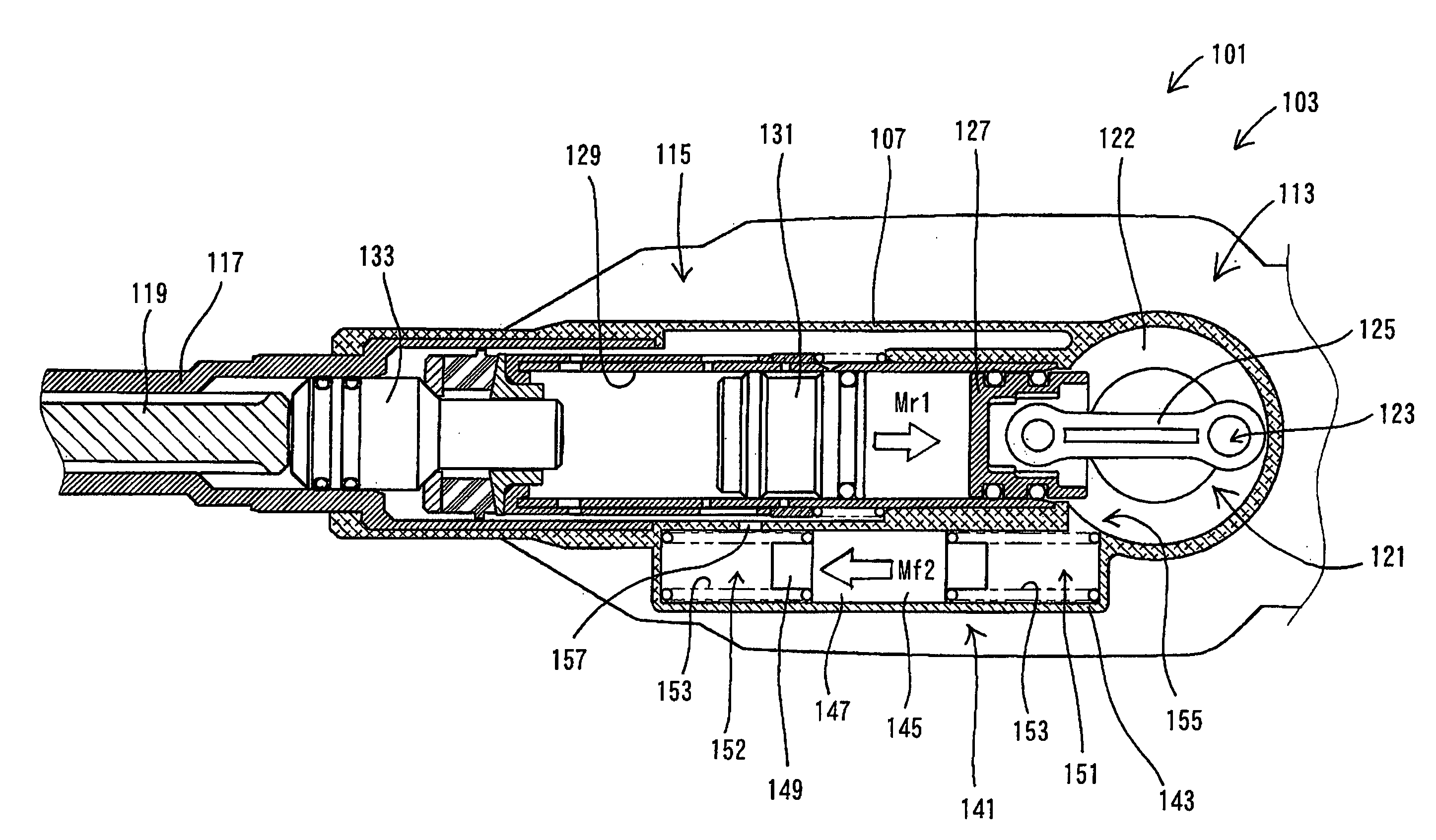
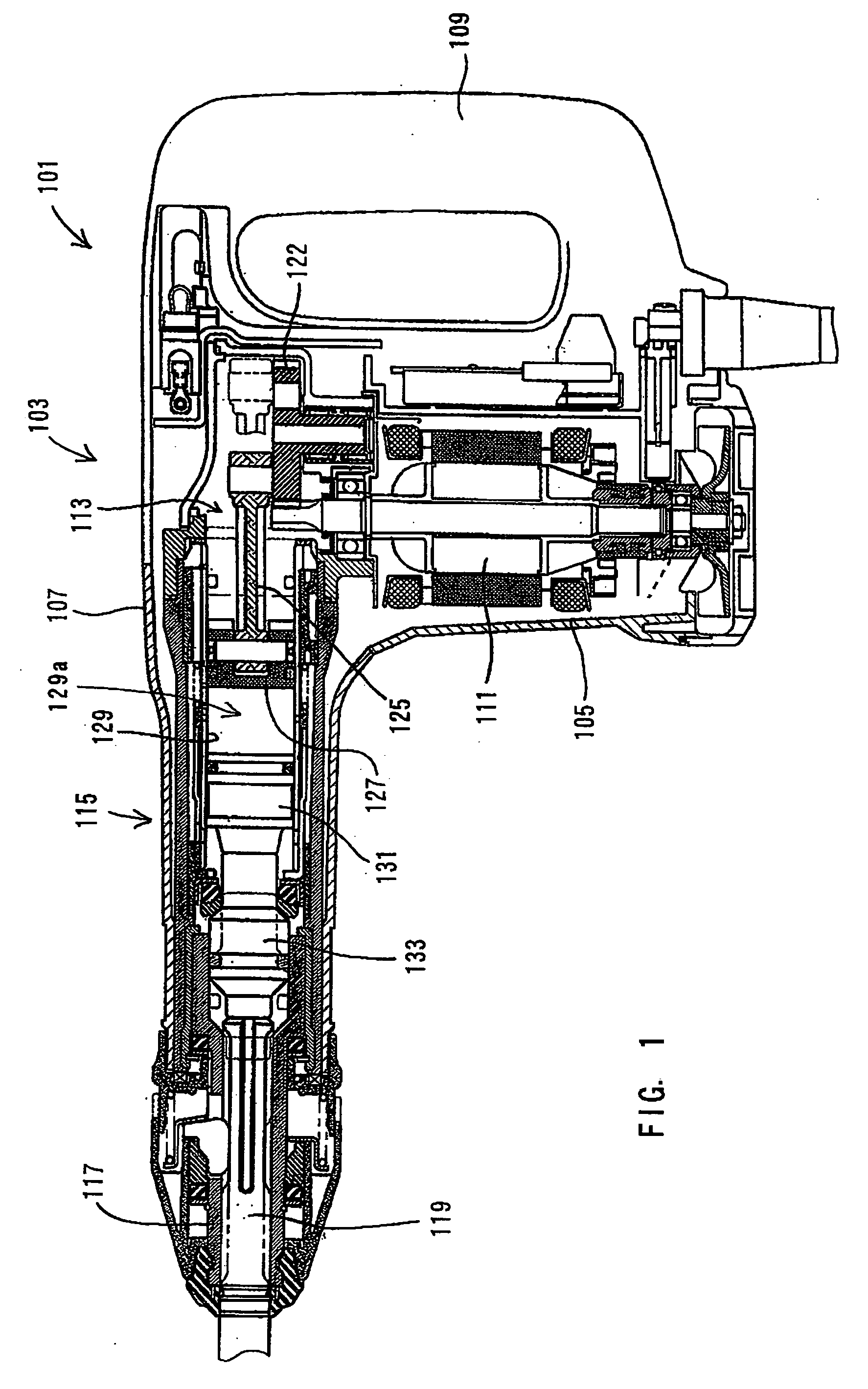
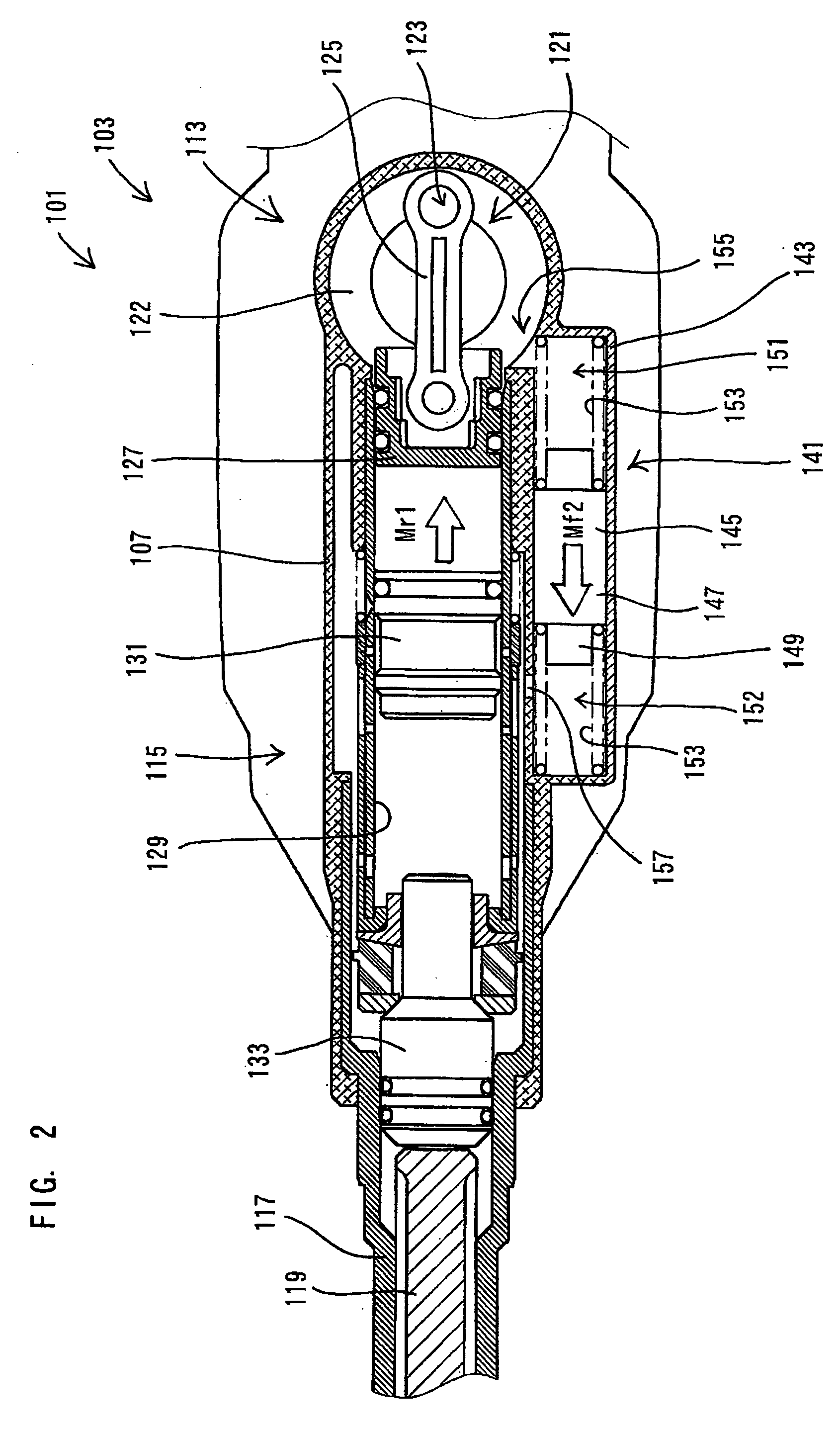
[0043] A first embodiment of the present invention will now be described with reference to FIGS. 1 to 5. An electric hammer will be explained as a representative example of the power tool according to the present invention. As shown in FIG. 1, a representative electric hammer 101 according to this embodiment comprises a body 103, a tool holder 117 connected to the tip end region of the body 103, and a hammer bit 119 that is detachably coupled to the tool holder 117. The hammer bit 119 is a feature that corresponds to the “tool bit” according to the present invention.

[0044] The body 103 includes a motor housing 105 that houses a driving motor 111, a gear housing 107 that houses a motion converting mechanism 113 and a striking element 115, and a handgrip 109. The motion converting mechanism 113 is adapted to appropriately convert the rotating output of the driving motor 111 to linear motion and then to transmit it to the striking element 115. As a result, an impact force is generated...

second embodiment

[0062] A second embodiment of the present invention will now be described with reference to FIGS. 6 and 7. In the second embodiment, a weight 245 of a dynamic vibration reducer 241 can be actively driven only under the loaded driving conditions in which a load is applied from the workpiece side to a hammer bit 219. For this purpose, a cylindrical actuating element 261 and a biasing spring 263 are fitted around a cylinder 229.

[0063] In FIG. 6, a hammer 201 is shown under the unloaded driving conditions in which no load is applied from the workpiece side to the hammer bit 219. At this time, the actuating element 261 is biased leftward as viewed in the drawing by the biasing spring 263. In this state, the actuating element 261 closes a first communicating portion 255 that communicates a first actuation chamber 251 of the dynamic vibration reducer 241 with the crank chamber 221. The actuating element 261 also closes a second communicating portion 257 that communicates a second actuatio...

third embodiment

[0068] A third embodiment of the present invention will now be described with reference to FIGS. 8 and 9. Like the second embodiment, the third embodiment is also constructed such that a weight 345 of a dynamic vibration reducer 341 can be actively driven only under the loaded driving conditions in which a load is applied from the workpiece side to a hammer bit 319. However, the third embodiment is different in construction from the second embodiment in the communicating state of a crank chamber 321 in the loaded and unloaded driving conditions. In a hammer 301 according to this embodiment, a cylindrical actuating element 361 and a biasing spring 363 are fitted around a cylinder 329. The crank chamber 221 is always in communication with a first actuation chamber 351 of the dynamic vibration reducer 341 via a first communicating portion 355.

[0069] In FIG. 8, the hammer 301 is shown under the unloaded driving conditions in which no load is applied from the side of the workpiece (not ...


PUM

PropertyMeasurementUnit
Weightaaaaaaaaaa
Forceaaaaaaaaaa
Pressureaaaaaaaaaa

Abstract

It is an object of the present invention to provide a power tool having a further improved vibration reducing performance. The representative power tool may comprise a tool bit, an actuating mechanism, a dynamic vibration reducer. The actuating mechanism drives the tool bit linearly by means of pressure fluctuations so as to cause the tool bit to perform a predetermined operation. The dynamic vibration reducer has a weight that reciprocates under a biasing force of an elastic element to reduce vibration of the actuating mechanism. The weight may be driven by means of pressure fluctuations caused in the actuating mechanism. According to the invention, the weight of the dynamic vibration reducer can be actively driven by pressure fluctuations in the actuating mechanism for driving the tool bit. Therefore, regardless of the magnitude of vibration acting on the power tool, the dynamic vibration reducer can be forcedly and steadily operated.

Description

BACKGROUND OF THE INVENTION [0001] 1. Field of the Invention [0002] The present invention relates to a power tool, and more particularly, to a technique of reducing vibration in a power tool, such as a hammer and a hammer drill, which linearly drives a hammer bit at a predetermined cycle. [0003] 2. Description of the Related Art [0004] Japanese Laid-Open Patent Publication No. 52-109673 discloses a hammer with a vibration reducing device. According to the known art, a vibration-isolating chamber is integrally formed within the body housing and a dynamic vibration reducer is housed within the vibration-isolating chamber. The dynamic vibration reducer serves to reduce vibration in relation to the amount of vibration inputted into the dynamic vibration reducer. Especially within the hammer, strong vibration may be developed in the axial direction of the hammer bit when the hammer is operated. [0005] In the above-explained dynamic vibration reducer, the weight is disposed under the acti...

Claims


Application Information

Patent Timeline
IPC IPC(8): B25D11/00B25D11/12B25D17/24
CPCB25D11/125B25D17/245B25D2211/003B25D2217/0084B25D2217/0092B25D2250/231B25D2250/371
Inventor AOKI, YONOSUKE
Owner MAKITA CORP
Why Eureka
Try Eureka