Coulomb friction damped disc brake rotors

a friction damped disc and brake rotor technology, applied in the direction of braking discs, noise/vibration control, mechanical equipment, etc., can solve the problems of inability unable to achieve the goal etc., to achieve the effect of reducing the thickness of the inser

Inactive Publication Date: 2006-04-13
GM GLOBAL TECH OPERATIONS LLC
View PDF81 Cites 104 Cited by
  • Summary
  • Abstract
  • Description
  • Claims
  • Application Information

AI Technical Summary

Benefits of technology

[0013] It is further believed that a Coulomb friction damped disc brake rotor according to the present invention has the following attributes: 1) the greater the surface area of the interfacial boundaries, the greater will be the damping; 2) the greater the number of interfacial boundaries, the greater will be the damping; 3) pre-tensioning and/or pre-loading is not requ

Problems solved by technology

Brake squeal can be undesirably generated at the brake corner when braking occurs.
And unfortunately, brake corners for performance motor vehicles, or those motor vehicles with high friction lining materials, are resistant to the prior art brake squeal countermeasures, due to the high amount of modal excitation from the friction material of the brake pads.
While the concept described in U.S. Pat. No. 5,855,257 is noteworthy in that an attempt is made to apply Coulomb friction damping t

Method used


Image

  • Coulomb friction damped disc brake rotors
  • Coulomb friction damped disc brake rotors
  • Coulomb friction damped disc brake rotors

Examples


Embodiment Construction

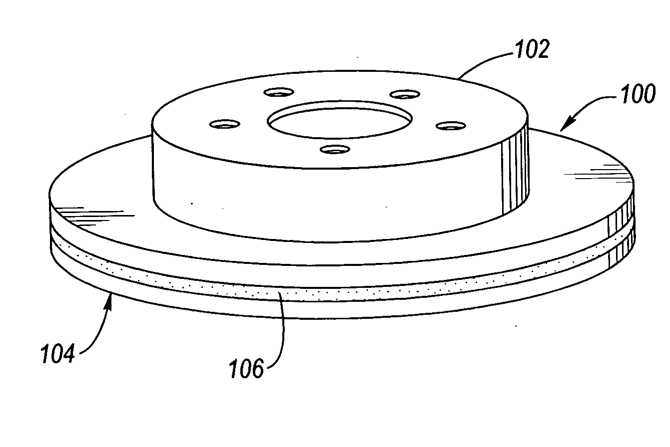
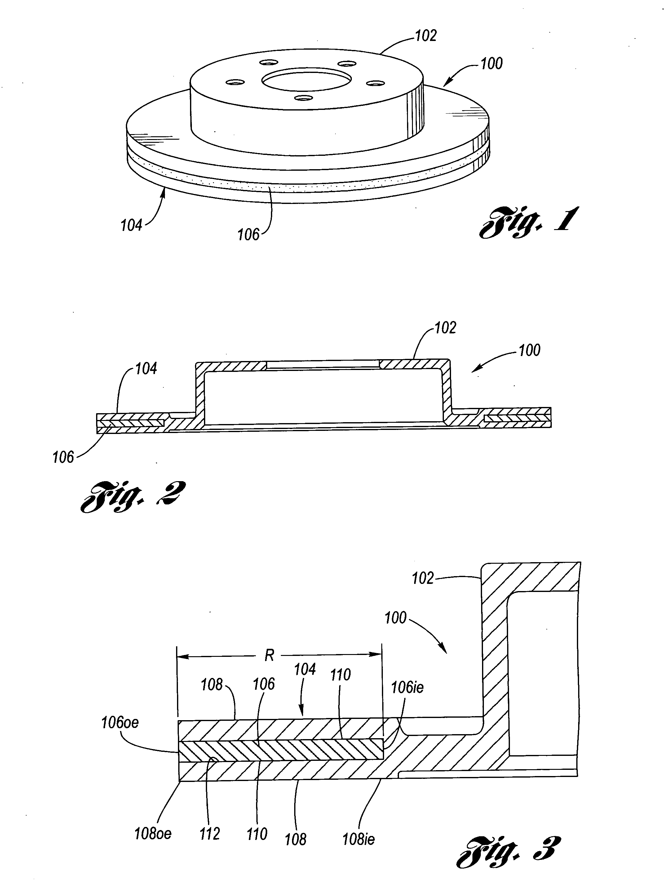
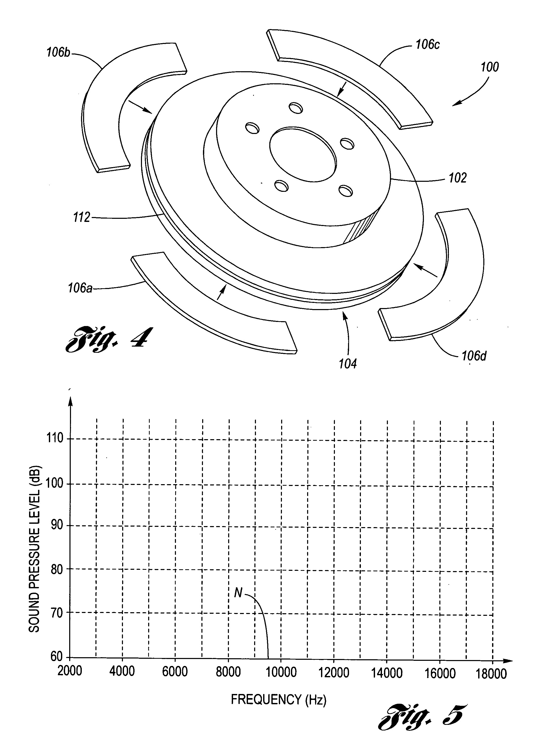
[0035] Referring now to the Drawing, FIGS. 1 through 7 depict various aspects of an example of a Coulomb friction damped disc brake rotor 100 for motor vehicle disc brake applications according to the present invention, FIGS. 8 through 12 depict various alternative configurations of a Coulomb friction damped disc brake rotor according to the present invention, and FIGS. 13A through 15M depict various examples of manufacturing methods for a Coulomb friction damped disc brake rotor according to the present invention.

[0036] Turning attention firstly to FIGS. 1 through 3, the Coulomb friction damped disc brake rotor 100 has, by way of non-limiting example, a rotor hat 102 (which need not be present for purposes of the present invention), a rotor cheek 104 of solid rotor cheek configuration, and an insert 106 disposed within the rotor cheek, wherein the insert is generally coextensive with the braking surfaces 108 of the rotor cheek. In this regard, the insert 106 radially extends, from...


PUM

PropertyMeasurementUnit
Moldableaaaaaaaaaa
Frictionaaaaaaaaaa

Abstract

A Coulomb friction damped disc brake rotor, wherein damping is provided Coulomb friction in generally coextensive relation with the braking surfaces of the one or more rotor cheeks. The Coulomb friction damped disc brake rotor has at least one interfacial boundary formed in at least one rotor cheek disposed in generally coextensive relation to the braking surface thereof. The interfacial boundary provides a mechanically distinguishable surface boundary between two surfaces which are in mutual contact such that a state of Coulomb friction exists therebetween.

Description

TECHNICAL FIELD [0001] The present invention relates to disc brake rotors used in automotive applications, and more particularly to Coulomb friction damped disc brake rotors in which the damping is provided by at least one interfacial boundary disposed in substantially coextensive relation with a braking surface of at least one rotor cheek thereof. BACKGROUND OF THE INVENTION [0002] Motor vehicle disc brake systems utilize a disc brake rotor at each respective wheel, wherein the disc brake rotor typically includes a rotor hat for connecting to an axle hub of a rotatable axle of the motor vehicle, and at least one annular rotor cheek connected to the rotor hat, wherein the at least one rotor cheek has a pair of mutually opposed braking surfaces onto which brake pads are selectively applied when braking is desired. Typically, the rotor cheek configuration may be solid, in which case a single rotor cheek has opposing braking surfaces thereon, or may be vented, in which case a pair of r...

Claims


Application Information

Patent Timeline
IPC IPC(8): F16D65/12
CPCF16D65/0018F16D65/125F16D2065/132F16D2065/1328F16D2200/0034
Inventor DESSOUKI, OMAR S.LOWE, BRENT D.RIEFE, MARK T.DOESCHER, MATTHEW T.SACHDEV, ANIL K.VERBRUGGE, MARK W.SCHROTH, JAMES G.HANNA, MICHAEL D.
Owner GM GLOBAL TECH OPERATIONS LLC
Why Eureka
Try Eureka