Method of manufacturing an SOI substrate and method of manufacturing a semiconductor device
a manufacturing method and semiconductor technology, applied in the direction of semiconductor devices, electrical appliances, basic electric elements, etc., can solve the problems of insufficient repair of the damage to the inability to heat treatment at a temperature of 1000° c. or more, and the damage of the silicon layer by the above ion irradiation step, etc., to achieve high reliability, high planarity, and high performance
- Summary
- Abstract
- Description
- Claims
- Application Information
AI Technical Summary
Benefits of technology
Problems solved by technology
Method used
Image
Examples
embodiment mode 1
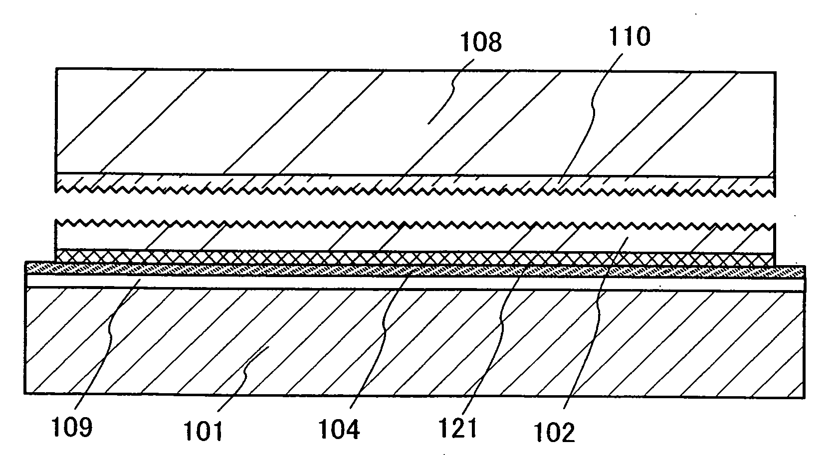
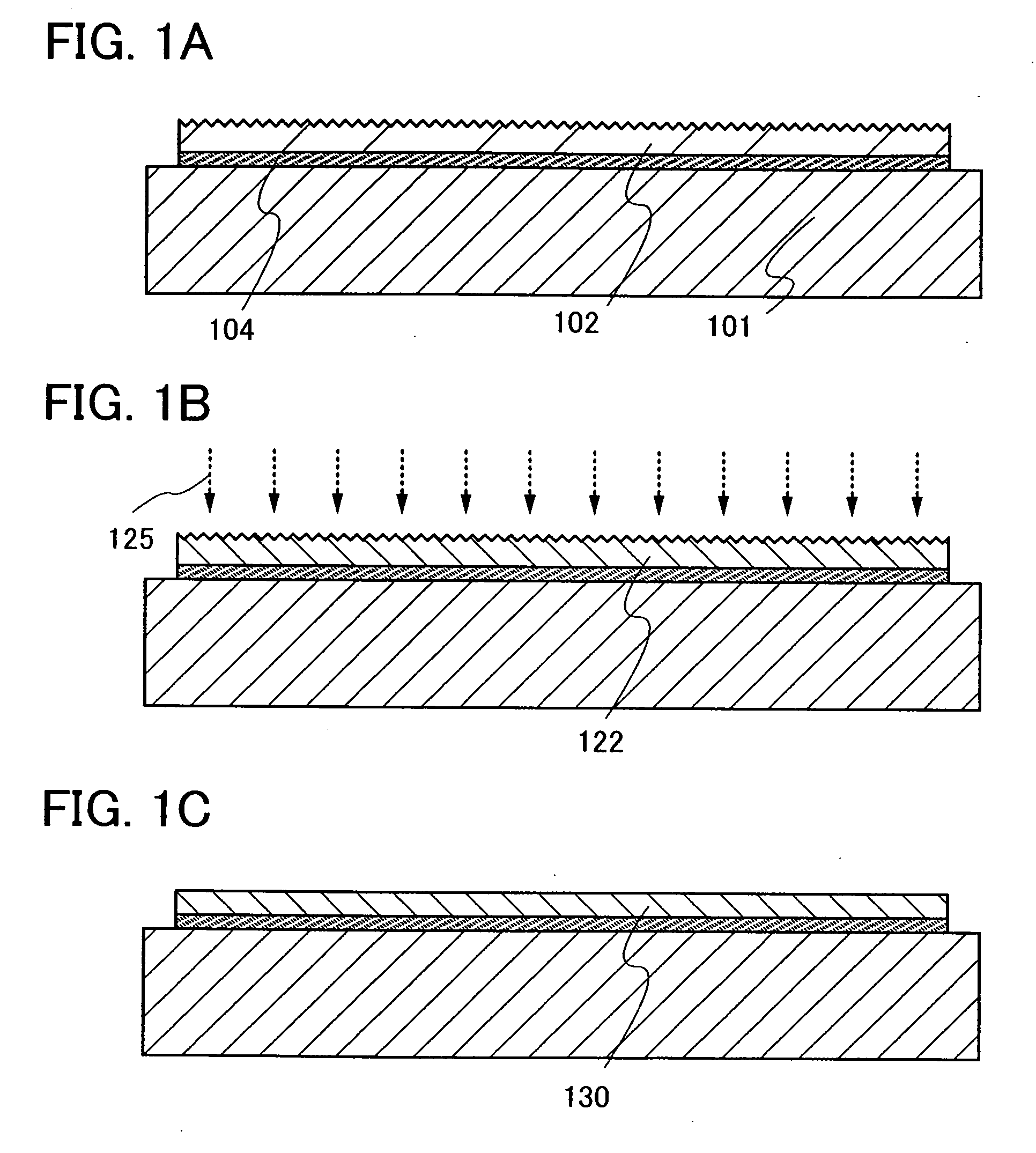
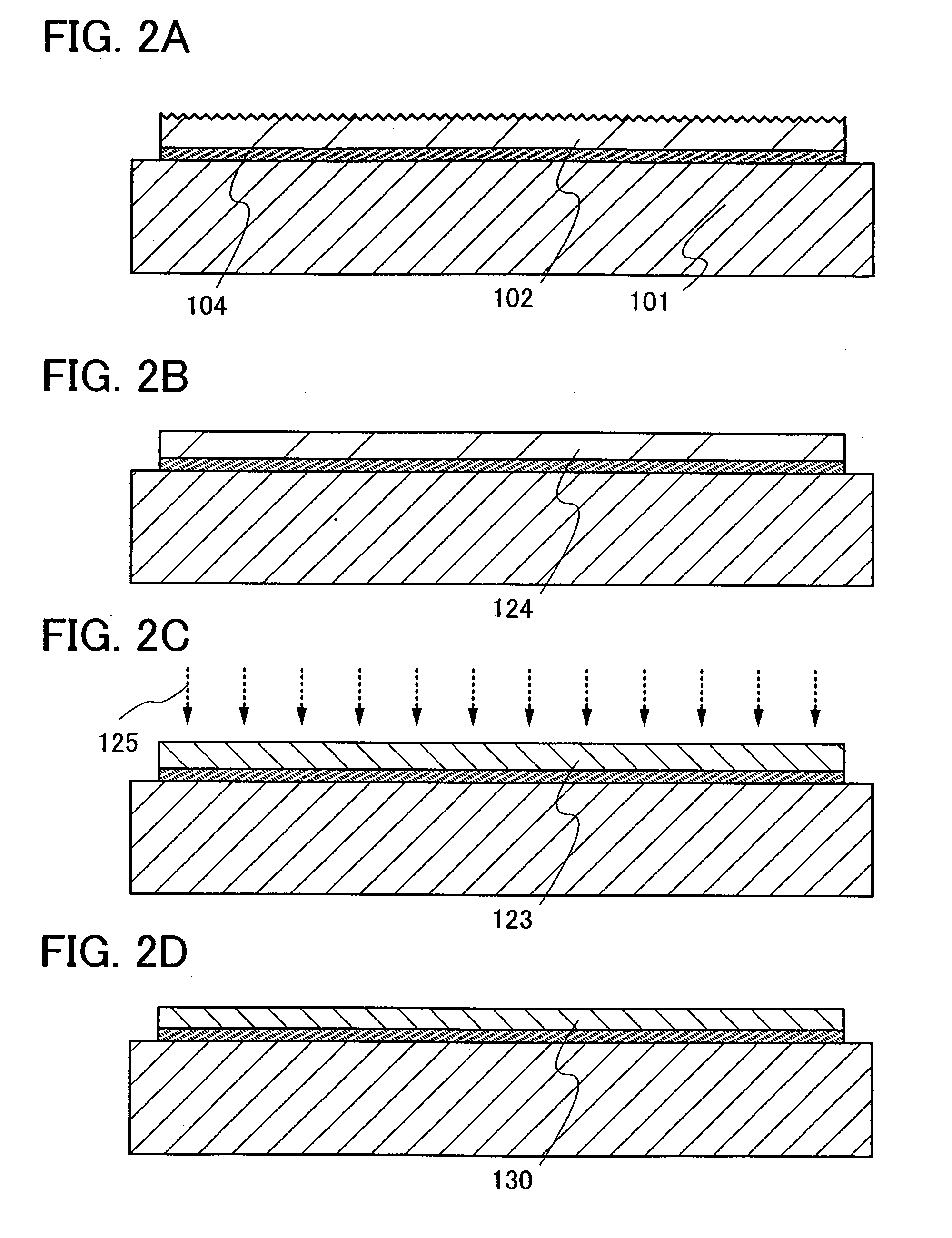
[0058]A method of manufacturing a semiconductor device of the present invention will be described with reference to FIGS. 1A to 1C, 2A to 2D, 3A to 3D, and 4A to 4C.
[0059]In this embodiment mode, a semiconductor layer, which is separated from a semiconductor substrate and bonded to a supporting substrate having an insulating surface, is irradiated with electromagnetic waves and the surface of the semiconductor layer which is irradiated with electromagnetic waves is subjected to polishing treatment. A single-crystal semiconductor substrate is preferably used as the semiconductor substrate, and a single-crystal semiconductor layer is preferably formed as the semiconductor layer which is separated from the semiconductor substrate and bonded to the supporting substrate.
[0060]First, a method of forming a semiconductor layer over a supporting substrate which is a substrate having an insulating surface by using a semiconductor substrate will be described with reference to FIGS. 3A to 3D an...
embodiment mode 2
[0123]In this embodiment mode, a method of manufacturing a CMOS (complementary metal oxide semiconductor) will be described as an example of a method of manufacturing a semiconductor device including a semiconductor element having high performance and high reliability with high yield with reference to FIGS. 5A to 5E and 6A to 6D. Note that repetitive descriptions for the same components as or components having similar functions to the components in Embodiment Mode 1 are omitted.
[0124]In FIG. 5A, the blocking layer 109, the insulating layer 104, the protective layer 121, and the semiconductor layer 130 are formed over the supporting substrate 101. The semiconductor layer 130 corresponds to FIG. 1C or 2D; and the blocking layer 109, the insulating layer 104, and the protective layer 121 correspond to FIG. 4C. Note that here, although an example is shown in which an SOI substrate having a structure shown in FIG. 5A is used, an SOI substrate having another structure shown in this specif...
embodiment mode 3
[0151]In this embodiment mode, an example of a method of manufacturing a semiconductor device (also referred to as a liquid crystal display device) having a display function as a semiconductor device having high performance and high reliability with high yield will be described with reference to FIGS. 7A and 7B. Specifically, a liquid crystal display device that includes a liquid crystal display element as a display element will be described.
[0152]FIG. 7A is a top view of a semiconductor device which is one mode of the present invention, and FIG. 7B is a cross-sectional view taken along a line C-D of FIG. 7A.
[0153]As shown in FIG. 7A, a pixel region 306 and driver circuit regions 304a and 304b which are scanning line driver circuits are sealed between a supporting substrate 310 and a counter substrate 395 with a sealant 392. In addition, a driver circuit region 307 which is a signal line driver circuit formed using a driver IC is provided over the supporting substrate 310. A transis...
PUM
 Abstract
Description
Claims
Application Information
 - R&D
- Intellectual Property
- Life Sciences
- Materials
- Tech Scout
- Unparalleled Data Quality
- Higher Quality Content
- 60% Fewer Hallucinations
Browse by: Latest US Patents, China's latest patents, Technical Efficacy Thesaurus, Application Domain, Technology Topic, Popular Technical Reports.
© 2025 PatSnap. All rights reserved.Legal|Privacy policy|Modern Slavery Act Transparency Statement|Sitemap|About US| Contact US: help@patsnap.com


