Semiconductor structure for a heterojunction bipolar transistor and a method of making same

a technology of heterojunction bipolar transistor and semiconductor structure, which is applied in the direction of semiconductor devices, basic electric elements, electrical apparatus, etc., can solve the problems of inability to apply inp-based hbts, and inability to meet the requirements of inp-based hbts

Inactive Publication Date: 2005-02-17
HRL LAB
View PDF15 Cites 21 Cited by
  • Summary
  • Abstract
  • Description
  • Claims
  • Application Information

AI Technical Summary

Benefits of technology

[0014] HBTs according to embodiments of the present invention have a thin and depleted emitter ledge layer portion that has no gaps between the emitter ledge portion and the base contacts, thus providing for 100% surface passivation of the surface of the base layer. Ledge thickness is known to be critical in making a ledge work properly for surface passivation. See, for example, W. Liu et al., “Parasitic Conduction Current in the Passivation Ledge of AlGaAs / GaAs Heterojunction Bipolar Transistors,” Solid State Electronics, Vol. 35, No. 7, pp. 891-895, 1992. Therefore, embodiments of the present invention provide for methods to control the thickness of the ledge layer and devices that have ledge layers with controlled thicknesses. The separation of the base contacts of the HBT and the emitter mesa is controlled by the length of the emitter ledge. The length of the depleted ledge portion is easily controlled by photo lithographic techniques well known in the art that can bring the base contacts as close to the emitter mesa as needed.
[0017] The manufacturability of InP-based HBTs according to embodiments of the present invention will be enhanced because the thickness and length of the emitter ledge can be controlled by conventional processes. Further, embodiments of the present invention provide for good contact between the base electrodes and the base layer.
[0018] The emitter ledge layer according to embodiments of the present invention also protects the base layer from being attacked in sequential process steps. Therefore it can be applied to both InP based SHBT (single hetero-junction HBT) and DHBTs (double hetero-junction HBTs) including InP / GaAsSb / InP DHBTs.
[0019] Essentially, the emitter ledge layer and the base contacts in embodiments according to the present invention serve to seal the base layer. Hence, the emitter ledge layer passivates the surface of the base layer to reduce base contact recombination current near the emitter-base junction.
[0020] Embodiments of the present invention may provide more planar device structure and potential for new interconnect design. Thus, embodiments of the present invention device may enhance large scale circuit integration for use in applications, such as radar and communication systems.
[0022] Another embodiment according to the present invention is a method for fabricating a heterojunction bipolar transistor (HBT) comprising: providing a substrate; forming a collector layer and a base layer for the HBT on the substrate; forming an emitter ledge layer above the base layer; forming an emitter mesa region above the emitter ledge layer; and forming one or more base contacts in the emitter ledge layer at selected distances from the emitter mesa, the one or more base contacts in electrical contact with the base layer, where the emitter ledge layer has an intrinsic region located beneath the emitter mesa and an extrinsic region located outside the intrinsic region and the extrinsic region comprises depleted semiconductor material and where the one or more base contacts are formed in the extrinsic region and one or more base contacts and the emitter ledge layer are formed so that there are no gaps in the extrinsic region of the emitter ledge layer between the one or more base contacts and the emitter mesa to leave an upper surface of the base layer exposed.

Problems solved by technology

However, fabrication techniques for InP-based HBTs are generally considered to be less developed than those for Gallium Arsenide (GaAs) based HBTs.
One key concern with GaAs-based HBTs is exposure of the GaAs base surface layer, since an exposed base surface layer is known to lead to unnecessary additional base currents.
However, thin and depleted emitter ledge passivation techniques have not been applied to InP-based HBTs, because it is generally believed that, in comparison to GaAs-based HBTs, the depleted emitter ledge passivation effect may manifest less influence on current gain, due to the lower surface recombination velocity of InGaAs.
However, InP-based NPN HBTs are not immune from external base surface recombination.
This recombination gives rise to the unnecessary and undesired base surface currents, and, especially, may be seen in scaled HBTs.
However, if the amount of overhang (which separates the base contact and the emitter mesa) is too small, the base surface and base contact recombination current may increase.
However, these processes for forming self-aligned HBTs, as indicated above, may be quite complicated and time consuming, leading to increased costs and decreased yields.
However, the layer design and process may not be suitable for scaled InP-based HBTs for use at high frequencies.
Further, formation of the thinned emitter edge may require additional and / or more complex fabrication steps than those used to form HBTs without a thinned emitter.
Some gaps result from unintentional misalignment in photolithography.

Method used


Image

  • Semiconductor structure for a heterojunction bipolar transistor and a method of making same
  • Semiconductor structure for a heterojunction bipolar transistor and a method of making same
  • Semiconductor structure for a heterojunction bipolar transistor and a method of making same

Examples


Embodiment Construction

[0031] Embodiments of the present invention will now be described more fully hereinafter with reference to the accompanying drawings. This invention may be embodied in many different forms and should not be construed as limited to the embodiments set forth herein. In the drawings, the thicknesses of layers and regions are exaggerated for clarity.

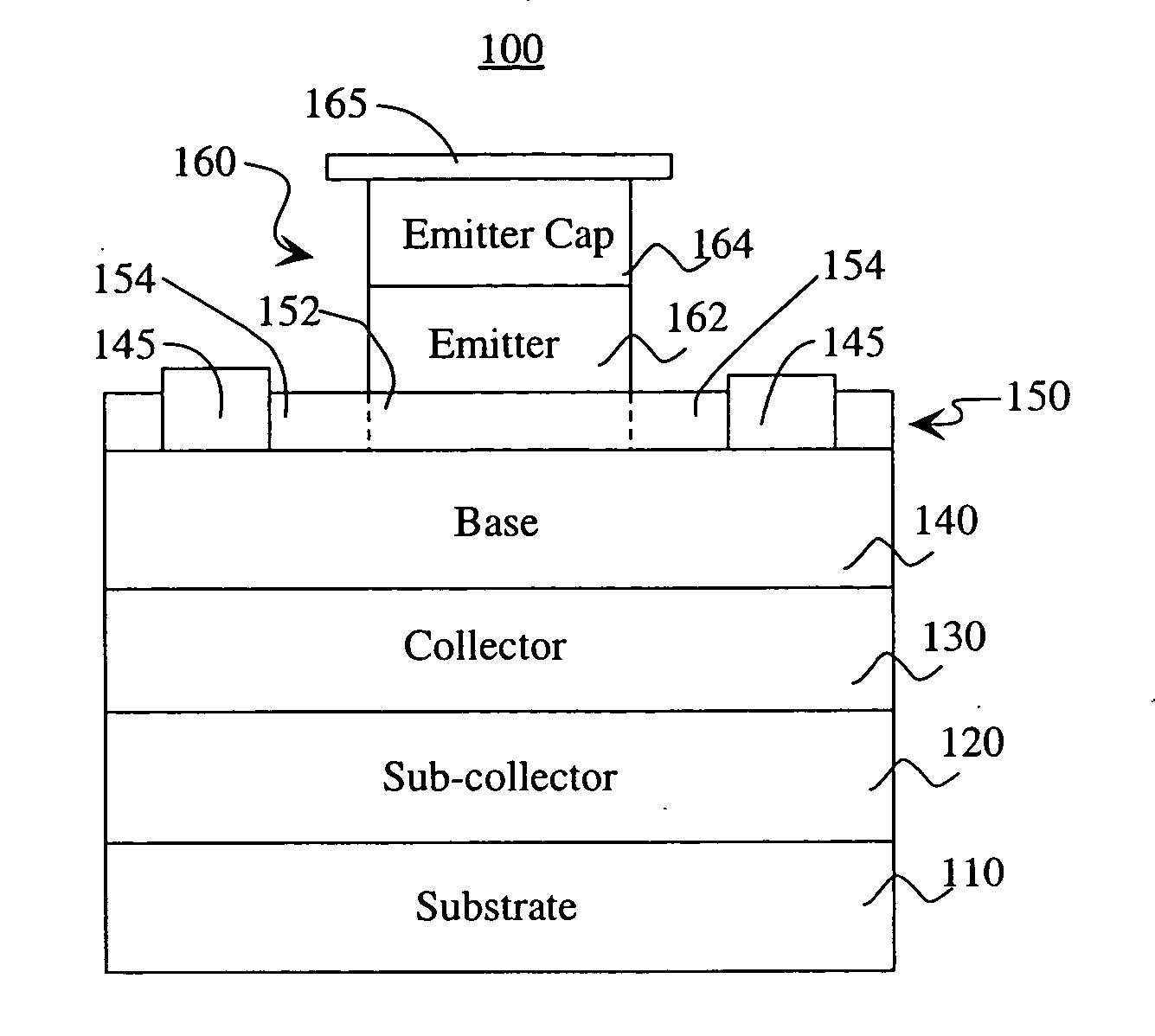
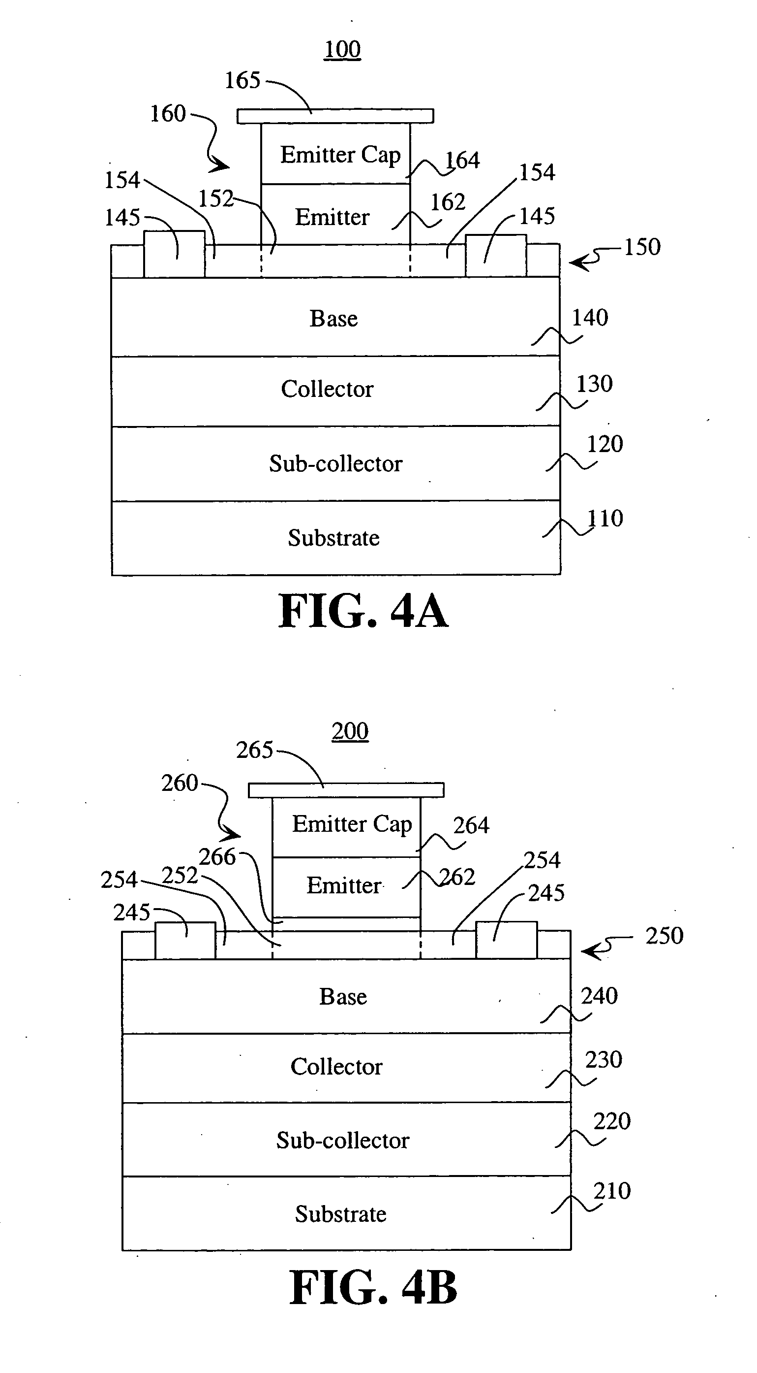
[0032]FIG. 4A shows the layers of an HBT 100 and its emitter and base contacts 145, 165 according to an embodiment of the present invention. The HBT 100 comprises a substrate layer 110, a sub-collector layer 120 disposed above the substrate layer 110, a collector layer 130 disposed above the sub-collector layer 120, a base layer 140 disposed above the collector layer 130, an emitter ledge layer 150 disposed above the base layer 140, and an emitter mesa 160 disposed above the emitter ledge layer 150. The emitter ledge layer 150 comprises an intrinsic region 152 that is located beneath the emitter mesa 160 and extrinsic region 154 that is loc...


PUM


Abstract

An InP based NPN heterojunction bipolar transistor (HBT) having an emitter mesa; a base layer; an emitter ledge layer located above the base layer and below the emitter mesa, the emitter ledge layer having an intrinsic region located beneath the emitter mesa and an extrinsic region located outside the intrinsic region, the extrinsic region made of depleted semiconductor material; and base contacts formed within a portion of the extrinsic region of the emitter ledge layer and spaced at selected distances from the emitter mesa, wherein the base contacts electrically contact the base layer, and wherein the base contacts and the emitter ledge layer are disposed to cover an upper surface of the base layer so that there are no gaps in the emitter ledge layer between the base contacts and the emitter mesa to leave the upper surface of the base layer exposed.

Description

CROSS REFERENCE TO RELATED APPLICATIONS [0001] The present application is related to and claims the benefit of co-pending U.S. Provisional Patent Application Ser. No. 60 / 494,693, filed on Aug. 12, 2003 and titled “A Semiconductor Structure For A Heterojunction Bipolar Transistor And A Method Of Making Same.” The disclosure of U.S. Provisional Patent Application No. 60 / 494,693 is incorporated herein by reference in its entirety.BACKGROUND [0002] 1. Field [0003] The present invention relates to Indium Phosphide (InP) based heterojunction bipolar transistors (HBTs). More particularly, the present invention relates to InP-based HBTs passivated with a thin depleted emitter ledge. [0004] 2. Description of Related Art [0005] InP-based HBTs are attractive for high-speed and low-power operation due to the inherent advantages of their material systems. These advantages result from excellent electron transport characteristics of their materials, such as high electron mobility, high peak electr...

Claims


Application Information

Patent Timeline
Patent Type & Authority Applications(United States)
IPC IPC(8): H01L21/331H01L29/08H01L29/737H01L31/0328
CPCH01L29/0817H01L29/7371H01L29/66318
Inventor CHEN, MARY
Owner HRL LAB
Why Eureka
Try Eureka