Brake control unit

a technology of brake control unit and control unit, which is applied in the direction of brake action initiation, vehicle components, braking system, etc., can solve problems such as significant jerking

Active Publication Date: 2006-04-13
HORIZON GLOBAL AMERICAS INC
View PDF72 Cites 68 Cited by
  • Summary
  • Abstract
  • Description
  • Claims
  • Application Information

AI Technical Summary

Benefits of technology

[0014] According to yet another embodiment of the present invention a method of controlling braking of a towed vehicle comprises receiving a deceleration signal based on deceleration of at least one of a towed vehicle, or a towing vehicle, or both the towing vehicle and the towed vehicle, increasing power supplied by a brake output signal to brakes of said towed vehicle until a present threshold deceleration is achieved for said towed vehicle, determining a braking power at which the preset threshold deceleration is achieved, and determining characteristics of the towed vehicle based on the deceleration.

Problems solved by technology

However, disclosures associated with such proposed brake control units have not disclosed how certain signals present on various automotive communication buses could be utilized to control and / or optimize control of brakes of a towed vehicle.
When towed vehicles are traveling at slower speeds, the electric brakes used to stop or slow down such towed vehicles are often too aggressive causing significant jerking, or in the worst case, locking of the brakes of the towed vehicle.

Method used


Image

  • Brake control unit
  • Brake control unit
  • Brake control unit

Examples


Embodiment Construction

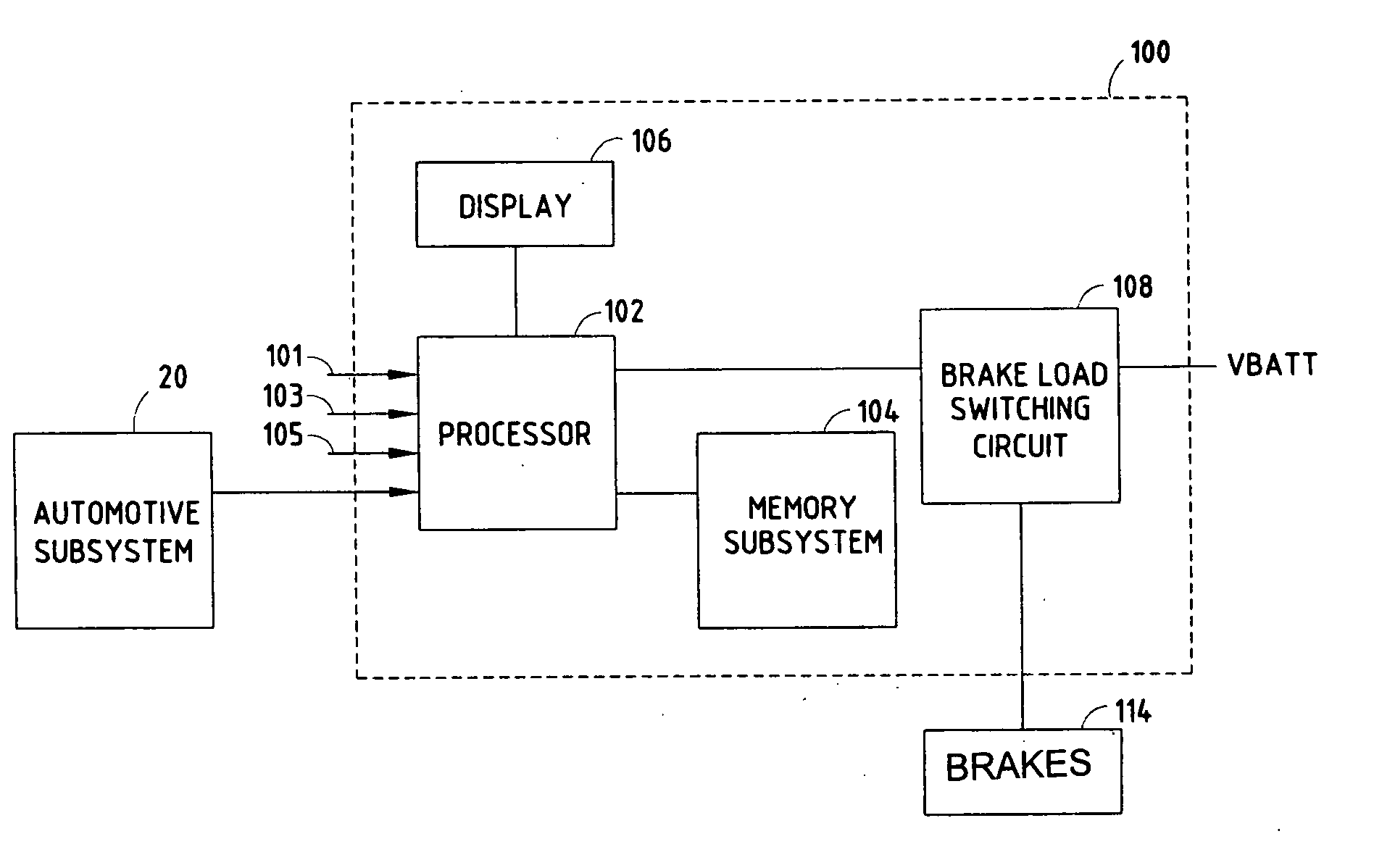
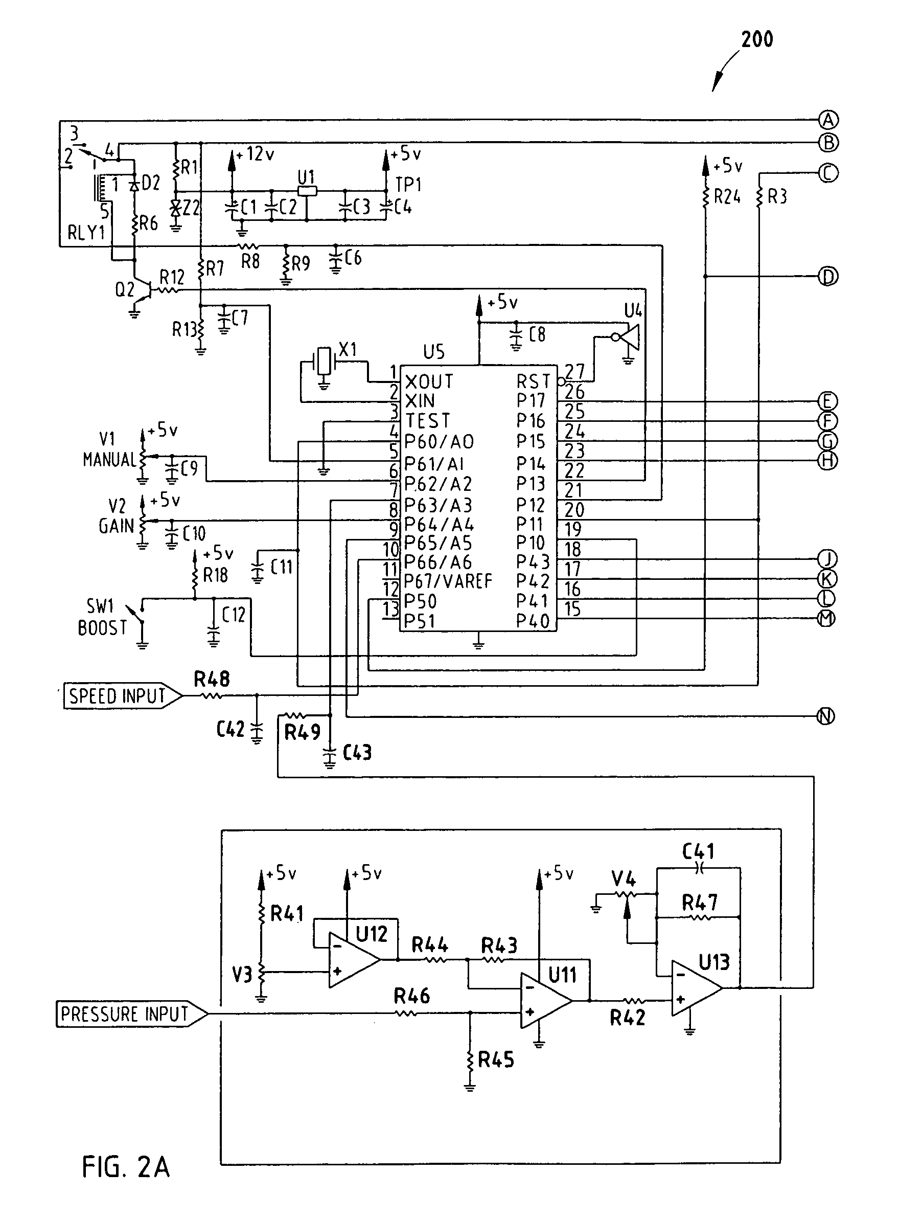
[0020] A brake control unit, according to an embodiment of the present invention, includes a processor and a memory subsystem. The brake control unit is typically located within a passenger compartment of a towing vehicle, and may even be integrated with the towing vehicle. For example, the brake control unit may be integrated in the dash of the towing vehicle. The processor is programmed to provide a brake output signal to brakes or brake load, e.g., electromagnetic brakes, of a towed vehicle responsive to one or more input signals, e.g., speed signals and pressure signals, that are provided by one or more automotive subsystems of the towing vehicle. The automotive subsystems may be coupled to the processor via an analog interface, a parallel bus, or a serial communication bus, e.g., a controlled area network or high-speed controlled area network (CAN) bus. Alternatively, the input signals may be provided by an automotive subsystem located on a towed vehicle or automotive subsystem...


PUM


Abstract

Towed vehicles can be extremely heavy. Accordingly, it is too much of a burden to the braking system of a towing vehicle to not have brakes on the towed vehicle. Controlling the brakes of the towed vehicle must be accurately applied otherwise very dangerous conditions can be created. A method of controlling braking of a towed vehicle is, therefore, needed. The method comprises receiving speed signals based on speed of a towing vehicle, or a towed vehicle, or both said towing vehicle and said towed vehicle, receiving pressure signals based on pressure of a hydraulic brake system of the towing vehicle, and generating a brake output signal based on the speed signals and the pressure signals.

Description

CROSS-REFERENCE TO RELATED APPLICATIONS [0001] This application claims priority from U.S. Provisional Patent Application No. 60 / 616,989 filed on Oct. 8, 2004, which is hereby incorporated by reference.FIELD OF THE INVENTION [0002] The present invention is generally related to a brake control unit, and more particularly to a brake control unit for providing a brake output signal to brakes of a towed vehicle. BACKGROUND OF THE INVENTION [0003] A variety of prior art brake control units that provide a brake output signal to brakes of a towed vehicle, such as a trailer, have been proposed and / or manufactured. A number of proposed brake control units have included a brake signal generator, e.g., a deceleration sensor, whose output has been utilized to determine a magnitude for the brake output signal. In general, these brake control units have proposed utilization of a signal provided by a component, located within a towing vehicle, to determine a magnitude for a brake output signal that...

Claims


Application Information

Patent Timeline
Patent Type & Authority Applications(United States)
IPC IPC(8): B60T7/20B60T8/66
CPCB60T7/20B60T8/323B60T8/1708
Inventor ALBRIGHT, MARCIAKULKARNI, CHANDRAKUMAR
Owner HORIZON GLOBAL AMERICAS INC
Why Eureka
Try Eureka