

Method and apparatus for detecting specific signal pattern in a signal read from an optical disc
a technology of optical discs and signals, applied in the direction of digital signal error detection/correction, instruments, television systems, etc., can solve the problems of increasing the complexity of circuitry designs, increasing the complexity of circuitry, and adding the difficulty of circuitry control
- Summary
- Abstract
- Description
- Claims
- Application Information
AI Technical Summary
Benefits of technology
Problems solved by technology
Method used
Image

Examples
first embodiment
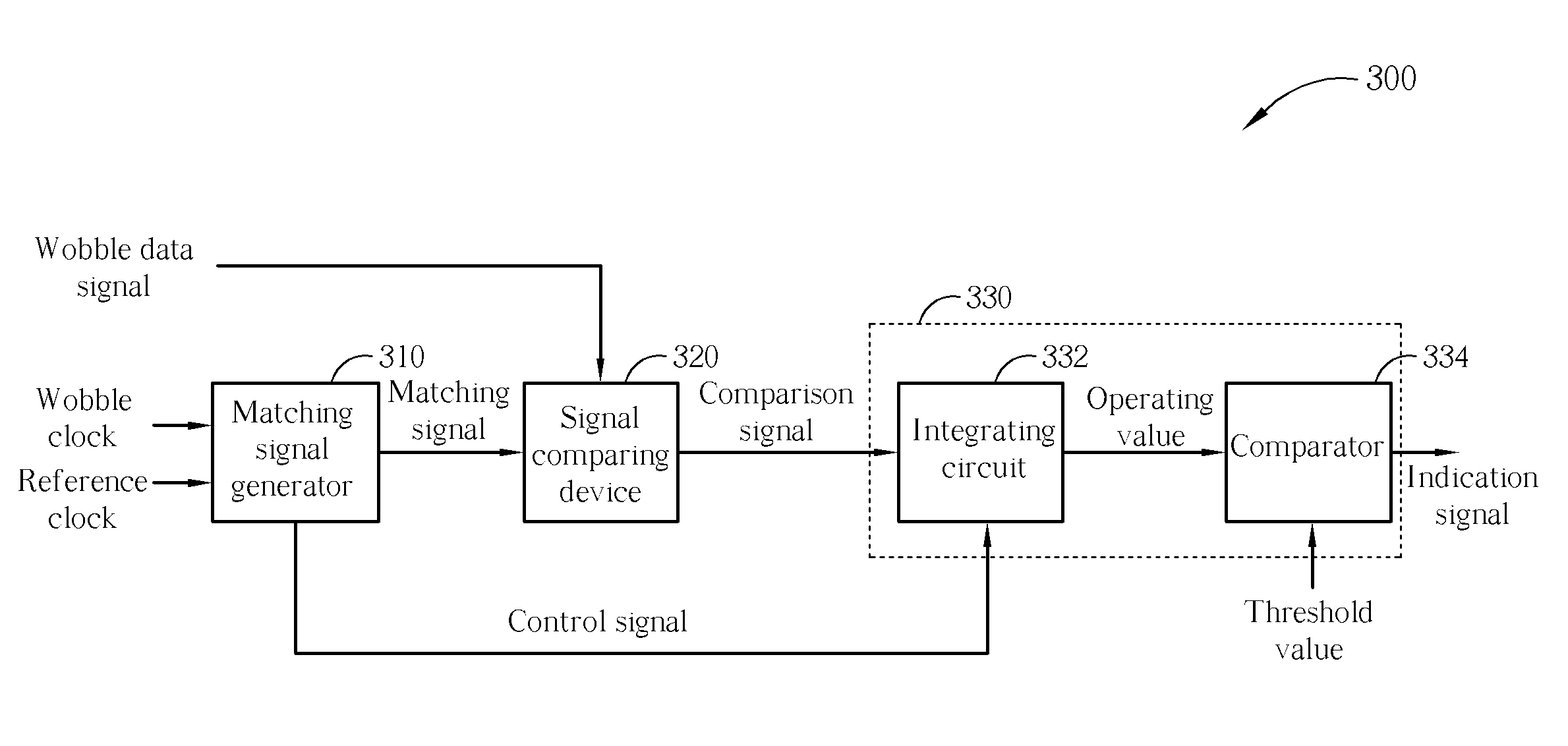
[0026]FIG. 6 shows a timing diagram 600 of the signal pattern detecting apparatus 300 according to a For convenient descriptions, both the wobble data signal and the matching signal are herein assumed to be binary signals. As shown, the wobble data signal comprises a MSK mark 602 having a length of three wobble periods. The other portions of the wobble data signal, excluding the MSK mark 602, are typically regarded as monotone. In this embodiment, waveforms that are identical to or similar as the MSK mark 602,such as the signal sections 612, 614, 616, and 618 shown in FIG. 6, repeatedly appear in the matching signal produced by the matching signal generator 310. In addition, in this embodiment, both the wobble data signal and the matching signal are assumed to be binary signals and the signal comparing device 320 can be implemented with a XNOR gate.
[0027] As mention previously, the signal comparing device 320 compares the waveform of the matching signal and the waveform of the wobb...
second embodiment
[0033] For example, FIG. 7 shows a timing diagram 700 of the signal pattern detecting apparatus 300 according to a In this embodiment, the matching signal produced from the matching signal generator 310 repeats a reversed waveform of a MSK mark 702, such as signal sections 712, 714, 716, and 718 shown in FIG. 7. Between a time point 710 and a time point 720, since the waveform of the signal section 714 of the matching signal is the reverse of the MSK mark 702, the comparison signal from the signal comparing device 320 maintains a logic low during that period. As a result, the computing result obtained by the integrating circuit 332, with respect to the period of the MSK mark 702, is less than the computing results obtained in other periods. Accordingly, the comparator 334 can decide whether to toggle an indication signal by comparing a sum (or a moving sum) of three consecutive operating values with a threshold value Th_value2. In this embodiment, when the sum (or moving sum) of th...
third embodiment
[0034]FIG. 8 shows a timing diagram 800 of the signal pattern detecting apparatus 300 according to a In this embodiment, the matching signal repeats a waveform similar or identical to the wobble clock, such as the signal shown in sections 812, 814, 816, and 818. In this embodiment, the signal pattern detecting apparatus 300 may produce the matching signal by utilizing the foregoing means. Alternatively, the signal pattern detecting apparatus 300 may simply employ the wobble clock as the matching signal. As shown in FIG. 8, between a time point 810 and a time point 820, the waveform of the signal section 814 of the matching signal is differ to a MSK mark 802. On the other hand, before the time point 810 or after the time point 820, the waveform of the matching signal is similar to or identical with the waveform of the wobble data signal. Therefore, the computing result obtained by the integrating circuit 332, with respect to the period of the MSK mark 802, will be less than the comp...
PUM
| Property | Measurement | Unit |
|---|---|---|
| threshold value | aaaaa | aaaaa |
| threshold | aaaaa | aaaaa |
| frequency | aaaaa | aaaaa |
Abstract
Description
Claims
Application Information