Terminal Apparatus

a technology of terminal apparatus and terminal cable, which is applied in the direction of data switching network, loop network, wireless communication, etc., can solve the problems of data transmission delay or data jitter, insufficient band, and inability to provide data transmission, so as to prevent the efficiency of communication medium use. , the effect of reducing the efficiency of communication medium

Active Publication Date: 2006-04-13
PANASONIC CORP
View PDF0 Cites 53 Cited by
  • Summary
  • Abstract
  • Description
  • Claims
  • Application Information

AI Technical Summary

Benefits of technology

[0015] Therefore, an object of the present invention is to provide a terminal apparatus for constructing a network on which a reduction in the efficiency of use

Problems solved by technology

These communication media are not dedicated media for high-speed digital communication, so that a sufficient band may not be provided and the reliability of data transmission may be poor.
Therefore, data transmission delay or data jitter is likely to occur.
However, when video, audio, or voice information is transmitted in packets, delay or jitter needs to be strictly limited.
Therefore, it is important and difficult to select a control terminal.
When a plurality of logical networks are created in a single communication medium controlled by the user as described above, data transmission between terminals may be redundant against the user's intention.
In such a ca

Method used


Image

  • Terminal Apparatus
  • Terminal Apparatus
  • Terminal Apparatus

Examples


first embodiment

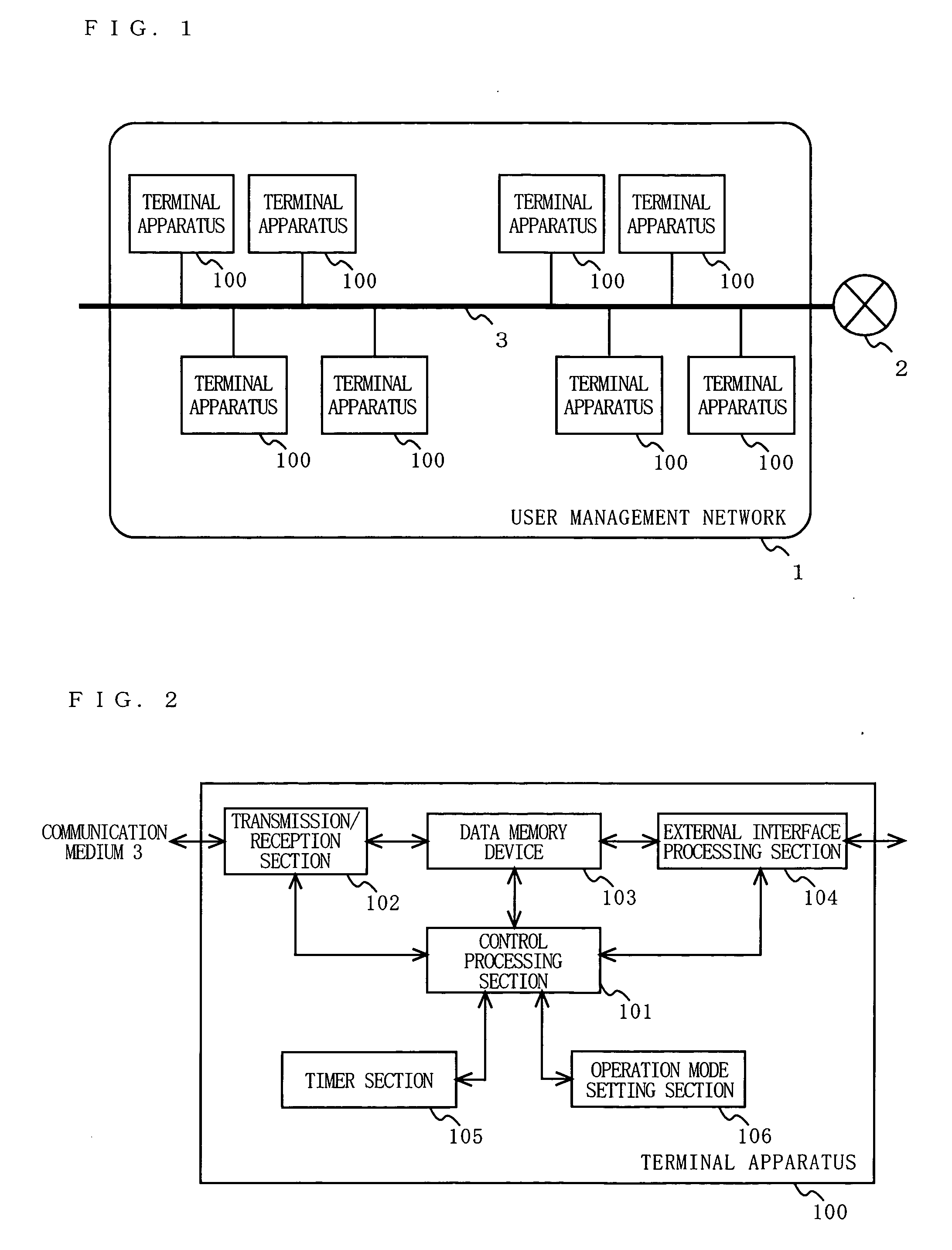
[0068]FIG. 1 is a diagram illustrating a structure of a whole system according to a first embodiment of the present invention. In FIG. 1, the system comprises a user management network 1 and an external network 2. The user management network 1 comprises a plurality of terminal apparatuses 100 which are connected together via a communication medium 3. Although eight terminal apparatuses 100 are illustrated in FIG. 1, the number of terminal apparatuses 100 is not limited to this. One terminal apparatus 100 transmits and receives a frame to and from at least one other terminal apparatus 100 via the communication medium 3. Although the communication medium 3 is illustrated as a wired medium in FIG. 1, it may be a wireless medium. On the user management network 1, for example, video transmission, audio transmission, voice transmission, Web browsing, file transfer, or the like is performed. The user management network 1 is operated in accordance with a centralized control type network con...

second embodiment

[0173] In the first embodiment, it is assumed that, after a failure is eliminated, a frame from each terminal apparatus reaches all terminal apparatuses. In the second embodiment, a method of unifying logical networks when a frame from each terminal apparatus does not reach all terminal apparatuses, will be described.

[0174] In the second embodiment, a structure of a whole system thereof is similar to that of the first embodiment, and will be described with reference to FIG. 1. Also in the second embodiment, a functional structure of each terminal apparatus is similar to that of the first embodiment, and will be described with reference to FIG. 2. In the second embodiment, each terminal apparatus can operate either in the control terminal mode or in the controlled terminal mode. Each terminal apparatus is assumed to have a function to, even if a control terminal has been once determined, change between a control terminal and a controlled terminal of a logical network, depending on t...

third embodiment

[0234] In the first and second embodiments, exemplary unification and interference of networks in which communication is performed with the same channel have been described. In a third embodiment, as an example, a network form which is used for wireless LAN or the like, and in which a transmission band is divided into a plurality of channels, will be described. The functional structure of each terminal is similar to that of the first embodiment and will be described with reference to FIG. 2. Note that the transmission / reception section 102 defines and manages channels divided in terms of frequency, and has a function to perform transmission / reception appropriate for a channel used in communication. In the third embodiment, each terminal apparatus can operate in a control terminal mode (hereinafter referred to as an access point mode in the third embodiment) or a controlled terminal mode (hereinafter referred to as a station mode in the third embodiment). Each terminal apparatus also...


PUM


Abstract

When operating as a control terminal and recognizing interference from another logical network, a terminal apparatus determines whether or not a logical network to be controlled is unified with the other logical network. When unification is determined, the terminal apparatus determines whether a control terminal of a logical network newly created by unification is the terminal apparatus or a control terminal of the other logical network.

Description

BACKGROUND OF THE INVENTION [0001] 1. Field of the Invention [0002] The present invention relates to a terminal apparatus which performs communication via a communication medium. More particularly, the present invention relates to a terminal apparatus which is used in a system which controls an opportunity to access a communication medium. [0003] 2. Description of the Background Art [0004] As broad-band access line infrastructures are built and widespread, and home network appliances are developed, there is a demand for construction of an infrastructure for a home network having an access line with high transmission ability. [0005] If an inexpensive and high-speed digital network can be constructed as a home network infrastructure without laying a new physical cable (hereinafter referred to as a physical communication dedicated cable), the user will have a great benefit. As a method which does not require a new physical communication dedicated cable, a method of using an existing wi...

Claims


Application Information

Patent Timeline
IPC IPC(8): H04L12/413
CPCH04L12/24H04L12/2803H04L12/2821H04L12/2838H04L12/40169H04L12/403H04L12/43H04L12/46H04L41/00H04L2012/2841H04L2012/2843H04L2012/2845H04W74/02
Inventor YAMAGUCHI, TSUYOSHIOHMI, SHINICHIROKURODA, GO
Owner PANASONIC CORP
Why Eureka
Try Eureka