
Condenser microphone

a condenser microphone and microphone technology, applied in the direction of electrical transducers, electrical transducers, transducer types, etc., can solve the problems of easy noise generation, high frequency impedance of point contact parts, and sometimes occurring noise on audio frequency bands, so as to achieve the effect of preventing nois

Active Publication Date: 2006-04-13
AUDIO-TECHNICA
View PDF2 Cites 9 Cited by
  • Summary
  • Abstract
  • Description
  • Claims
  • Application Information

AI Technical Summary

Benefits of technology

The present invention provides a side-entry condenser microphone with an effective noise prevention feature. The microphone includes a metallic head case portion and a metallic body portion for supporting the head case portion. A circuit board with an audio output circuit is fitted in the lower opening of the head case portion to close the lower opening and prevent the detection of electromagnetic waves. This prevents noise from being generated by external electromagnetic waves. The microphone also allows for performance inspection and defective component replacement during assembly. Additionally, a gland pattern on the circuit board and an allover pattern on the opposite side enhance the electrostatic shield and further prevent noise.

Problems solved by technology

If strong electromagnetic waves are applied from the outside, they are detected by the impedance converter, and hence noise sometimes occurs on an audio frequency band.
However, the electrical connection between these members is due to mechanical point contact, so that the point contact portion has an impedance in terms of high frequency.
Thereupon, the conventional example has a problem in that strong electromagnetic waves generated by a cellular phone etc. intrude from the point contact portion (connecting portion of these members) having an impedance in terms of high frequency into the microphone, whereby noise is generated easily.

Method used


Image

  • Condenser microphone
  • Condenser microphone
  • Condenser microphone

Examples


Embodiment Construction

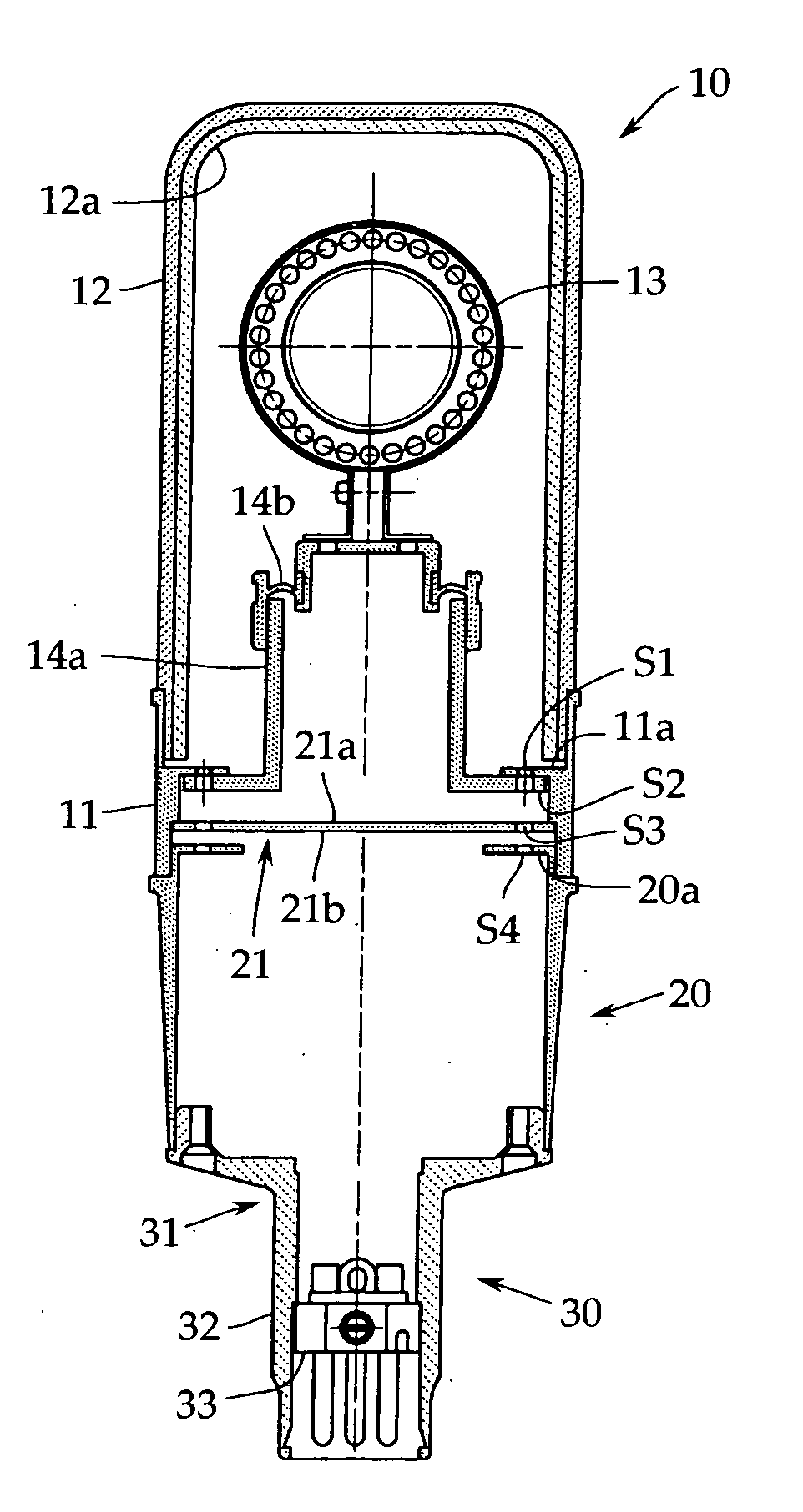
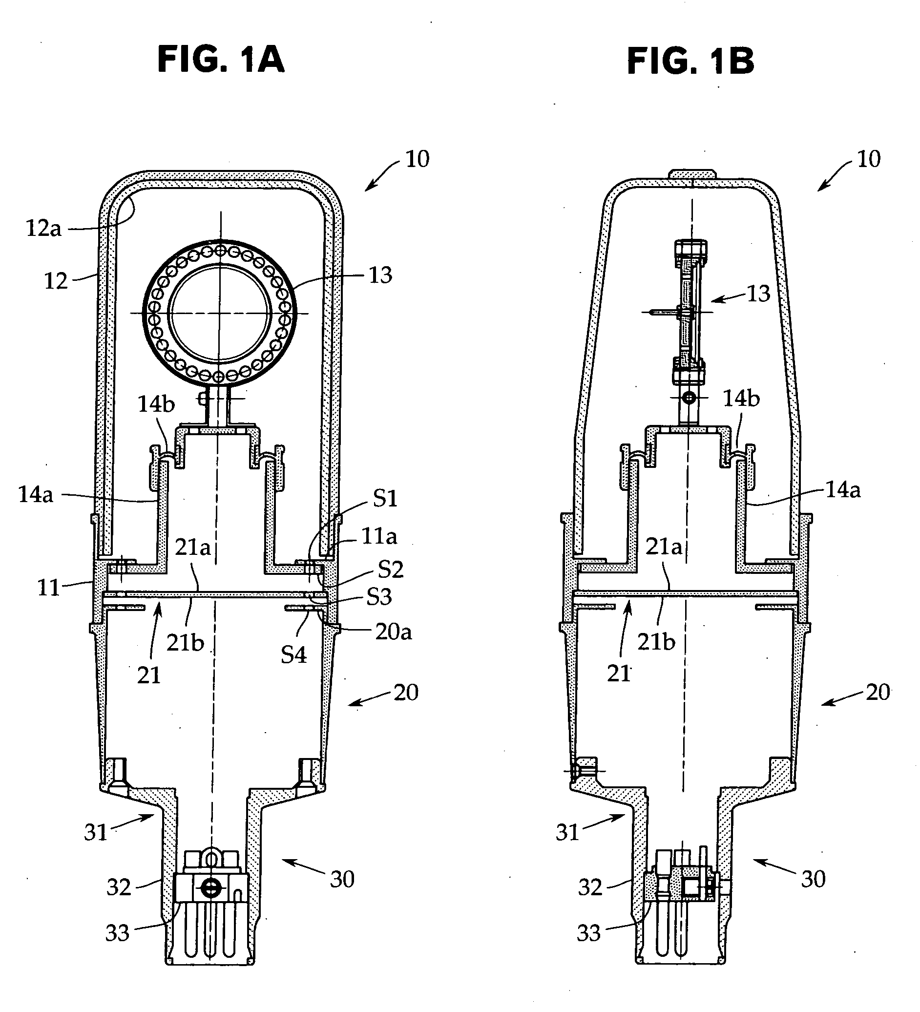
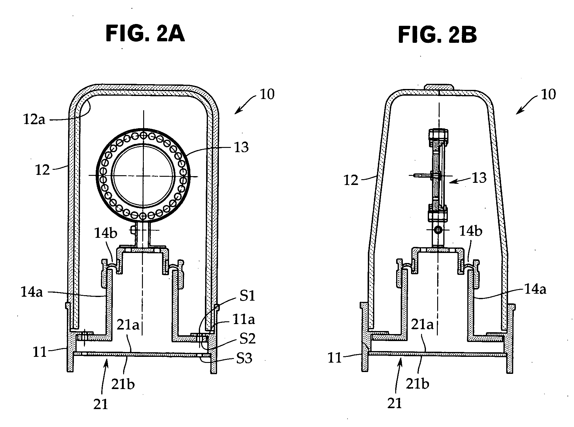
[0025] An embodiment of the present invention will now be described with reference to FIGS. 1 and 2. The present invention is not limited to this embodiment. FIGS. 1A and 1B are a front longitudinal sectional view and a side longitudinal sectional view showing one example of a side-entry condenser microphone in accordance with the present invention, respectively. FIGS. 2A and 2B are a front longitudinal sectional view and a side longitudinal sectional view of a head case portion, which is an essential portion of the present invention, respectively. The same reference characters are applied to elements that need not be changed from the conventional example explained with reference to FIGS. 3 and 4.

[0026] Like the conventional example explained before, the side-entry condenser microphone of this embodiment also includes a head case portion 10, a body portion 20 for supporting the head case portion 10 at the upper end thereof, and a connector portion 30 mounted at the lower end of the...


PUM


Abstract

In a side-entry condenser microphone, noise is prevented effectively from being generated by electromagnetic waves coming from the outside. In a side-entry condenser microphone including a metallic head case portion 10 which is covered with a metallic guard net 12 at an upper part thereof and is formed into a substantially cylindrical shape in which a microphone unit 13 is arranged via support members 14a and 14b in an internal space, and a metallic body portion 20 for supporting the head case portion 10 at the upper end thereof, a circuit board 21 mounted with an audio output circuit including an impedance converter is fitted in a lower opening of the head case portion 10 supported on the body portion 20 so as to close the lower opening with the circuit mounting surface 21a of the circuit board 21 being on the case inner surface side. Thereby, an electrostatic shield is completed by the head case portion 10 only.

Description

TECHNICAL FIELD [0001] The present invention relates to a condenser microphone. More particularly, it relates to a technique for protecting a side-entry condenser microphone used exclusively at a studio from electromagnetic waves coming from the outside. BACKGROUND ART [0002] In a condenser microphone, since the impedance of a microphone unit thereof is very high, an impedance converter such as a field effect transistor (FET) and a vacuum tube is used. If strong electromagnetic waves are applied from the outside, they are detected by the impedance converter, and hence noise sometimes occurs on an audio frequency band. [0003] In recent years, cellular phones have come into wide use rapidly. At the time of transmission of cellular phone, very strong electromagnetic waves are radiated, so that countermeasures against electromagnetic waves have been required even in the side-entry condenser microphone used exclusively at a studio. FIGS. 3A and 3B are a front longitudinal sectional view ...

Claims


Application Information

Patent Timeline
Patent Type & Authority Applications(United States)
IPC IPC(8): H04R25/00
CPCH04R19/00
Inventor AKINO, HIROSHI
Owner AUDIO-TECHNICA
Learn More