Image matching apparatus, method of matching images, and computer program product

a technology of image matching and image, applied in the field of image matching apparatus, method of matching images, and computer program products, can solve the problems of inability to maintain such a quality, difficulty in dealing with fast motion, and inability to solve problems such as problems,

Inactive Publication Date: 2006-04-13
KK TOSHIBA
View PDF15 Cites 21 Cited by
  • Summary
  • Abstract
  • Description
  • Claims
  • Application Information

AI Technical Summary

Problems solved by technology

The conventional image matching techniques, however, are not immune to problems.
The optical flow methods, being sensitive to noises by nature, have difficulties in dealing with fast motion.
The block-based methods which perform the image matching for each block in the image, though presenting a high reliability in processing of motions such as horizontal translation of an object in the image, basically cannot maintain such a quality when the object in the image is, for example, transformed or rotated.
The gradient methods which perform the matching in the direction of descent of the luminance gradient of the image have difficulties in constantly searching the motion of the object.
Further, in the Bayesian methods, a global optimal

Method used


Image

  • Image matching apparatus, method of matching images, and computer program product
  • Image matching apparatus, method of matching images, and computer program product
  • Image matching apparatus, method of matching images, and computer program product

Examples


first embodiment

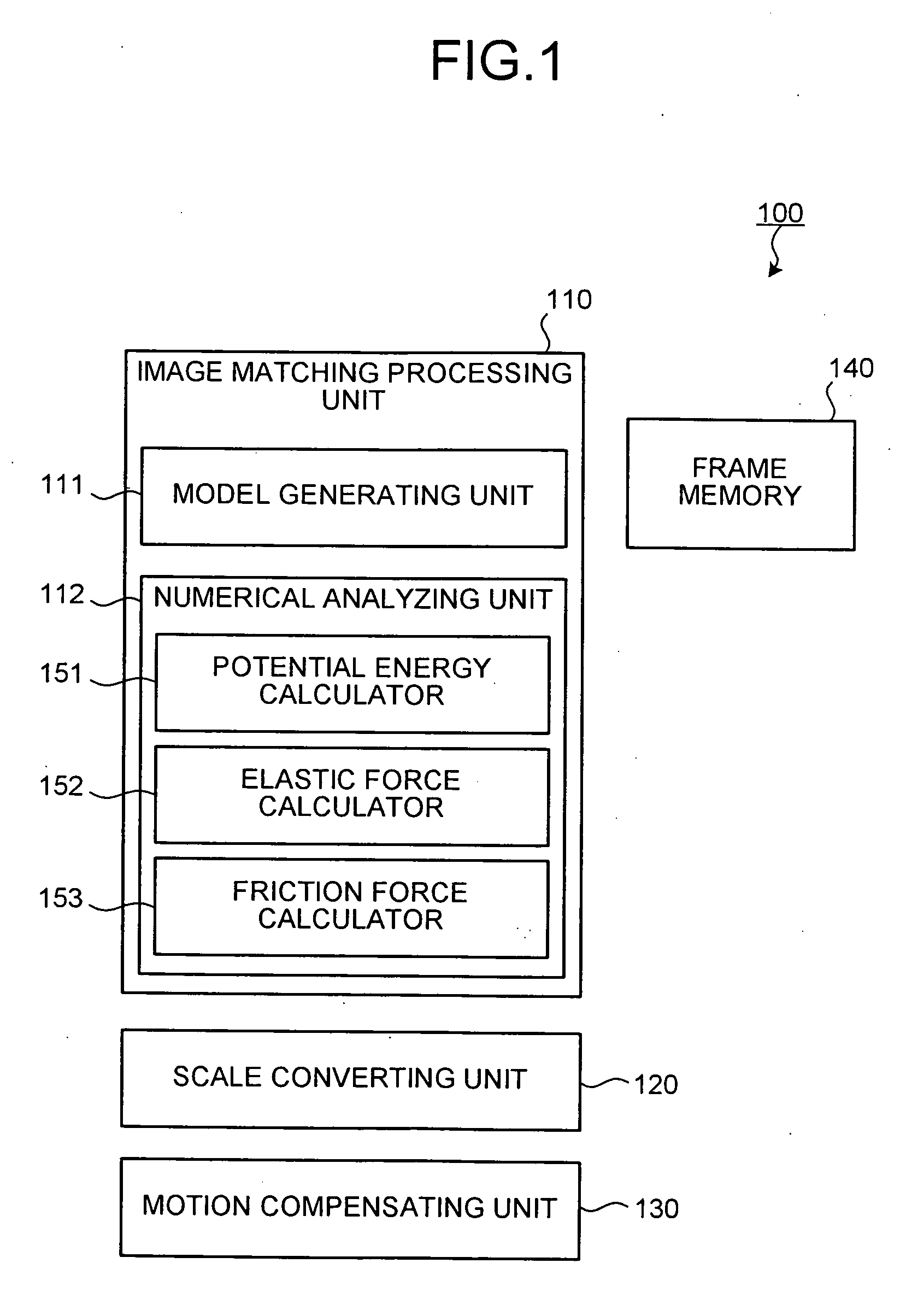
[0070]FIG. 1 is a block diagram of a functional structure of a motion compensating apparatus according to a first embodiment. The motion compensating apparatus according to the first embodiment, as shown in FIG. 1, mainly includes an image matching processing unit 110, a scale converting unit 120, a motion compensating unit 130, and a frame memory 140.

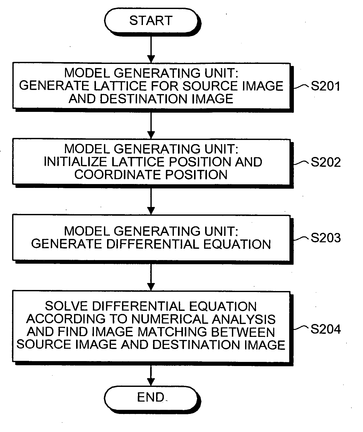
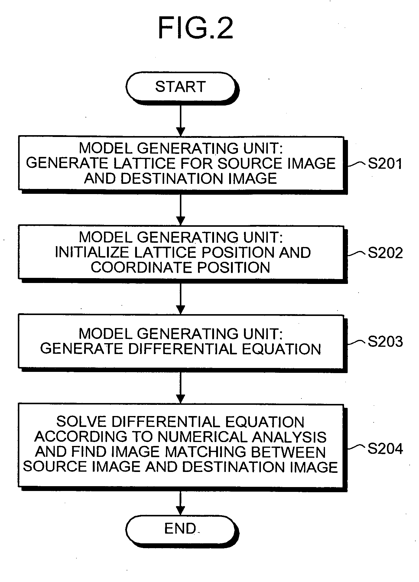
[0071] The image matching processing unit 110 selects any two images (as a starting image and a ending image) from an input image stream and performs a matching process on the starting image (source image) and the ending image (destination image). The image matching processing unit 110 includes a model generating unit 111 and a numerical analyzing unit 112.

[0072] The model generating unit 111 serves to create a dynamic image matching state transition model which is represented as an ordinary differential equation related with a position and a velocity of each point on the destination image. Each point on the destination image is mapp...

second embodiment

[0137] Next, a second embodiment will be described.

[0138] In the motion compensating apparatus according to the first embodiment, the state transition model is formulated based on the force of the potential energy of the luminance gradient of only a single pixel at each lattice point. Hence, when the target pixel contains the noise component, the potential space becomes complicated to cause distortion resulting in a longer time for the convergence of the model.

[0139] Hence, in a motion compensating apparatus according to the second embodiment, a target is set as a block consisting of plural pixels for the generation of the image matching state transition model. When the block consisting of plural pixels is set as the target of the model according to the second embodiment, the improvement in the robustness of the apparatus can be realized similarly to the block matching method.

[0140] The functional structure of the motion compensating apparatus according to the second embodiment i...

third embodiment

[0145] Next, a third embodiment is described.

[0146] In the motion compensating apparatus according to the first or the second embodiment, the image matching state transition model works according to the force of the potential of the pixel gradient at each lattice point. Hence, when the pixel gradient is not properly generated, for example, when the motion of the image is rough, the system of the image matching state transition model as represented by Equation (17) does not converge to a desired equilibrium position, thereby sometimes failing to realize an appropriate image matching.

[0147] Hence, in a motion compensating apparatus according to the third embodiment, downsampling is performed on the source image and the destination image plural times in a spatial direction, to generate hierarchical structures of the images. The processing is implemented sequentially from the upper layer to the lower layer of the hierarchical structures.

[0148] The functional structure of the motion c...


PUM


Abstract

An image matching apparatus includes a numerical analyzing unit that solves an equation of motion numerically. The equation of motion is formulated as an image matching state transition model representing a mapping relation between a source image and a destination image. The equation of motion represents a force applied on each lattice point of the destination image including potential energy force. The numerical analyzing unit calculates the potential energy force, and sets a convergence value of a solution of the equation of motion as a mapping relation between the lattice point of the source image and the lattice point of the destination image based on the numerical analysis.

Description

CROSS-REFERENCE TO RELATED APPLICATIONS [0001] This application is based upon and claims the benefit of priority from the priority Japanese Patent Application No. 2004-285241, filed on Sep. 29, 2004; the entire contents of which are incorporated herein by reference. BACKGROUND OF THE INVENTION [0002] 1. Field of the Invention [0003] The present invention relates to an image matching apparatus which detects corresponding points in a source image and a target image to associate the same with each other, a method of matching images, and computer program product therefor. [0004] 2. Description of the Related Art [0005] Image matching is a technique for detecting corresponding points of respective pixels in one source image (starting image) from another destination image (ending image) to find correspondence therebetween. The image matching techniques are utilized in various image processing such as motion detection of moving pictures, stereo matching, image morphing, image recognition, ...

Claims


Application Information

Patent Timeline
IPC IPC(8): G06K9/62
CPCG06K9/6206G06V10/754
Inventor MISHIMA, NAOITO, GOBABA, MASAHIRO
Owner KK TOSHIBA
Why Eureka
Try Eureka