Compressor assembly having counter rotating motor and compressor shafts

a compressor shaft and counter rotating technology, which is applied in the direction of machines/engines, positive displacement liquid engines, pumping pumps, etc., can solve the problems of increasing the cost and size of the compressor, the practical upper limit, and the excessive torsional vibration of the compressor assembly, so as to eliminate the torsional vibration

Active Publication Date: 2006-04-13
BLACK & DECKER INC
View PDF7 Cites 12 Cited by
  • Summary
  • Abstract
  • Description
  • Claims
  • Application Information

AI Technical Summary

Benefits of technology

[0006] Accordingly, the present invention is directed to a compressor assembly suitable for use in a compressor such as an air compressor, or the like, having counter rotating motor and compressor shafts with mass moments of inertia balanced to substantially eliminate torsional vibration.
[0007] In exemplary embodiments, the compressor assembly includes a compressor coupled to a motor (e.g., an electric motor, an engine, or the like) via a belt drive. The belt drive provides a speed reduction between the motor and compressor and causes the compressor shaft to rotate in the direction opposite that of the motor shaft. The relative values of the mass moments of inertia about the axes of rotation of the rotating motor and compressor shafts are engineered to be generally inversely proportional to the relative shaft speeds. In this manner, the mass moments of inertia may be balanced to substantially eliminate torsional vibration.

Problems solved by technology

A significant problem with reciprocating piston compressors is that the torque of the compressor shaft varies significantly during rotation of the shaft (i.e., reciprocation of the piston) causing excessive torsional vibration of the compressor assembly.
These solutions add cost and size to the compressor and have practical upper limits.
However, this solution also generates excessive noise and increases reciprocating imbalance.
Moreover, the effectiveness of all three solutions is limited to reduction rather than elimination of torsional vibration and requires compromise between the types of imbalance and noise reduction.

Method used


Image

  • Compressor assembly having counter rotating motor and compressor shafts
  • Compressor assembly having counter rotating motor and compressor shafts
  • Compressor assembly having counter rotating motor and compressor shafts

Examples


Embodiment Construction

[0016] Reference will now be made in detail to the presently preferred embodiments of the invention, examples of which are illustrated in the accompanying drawings.

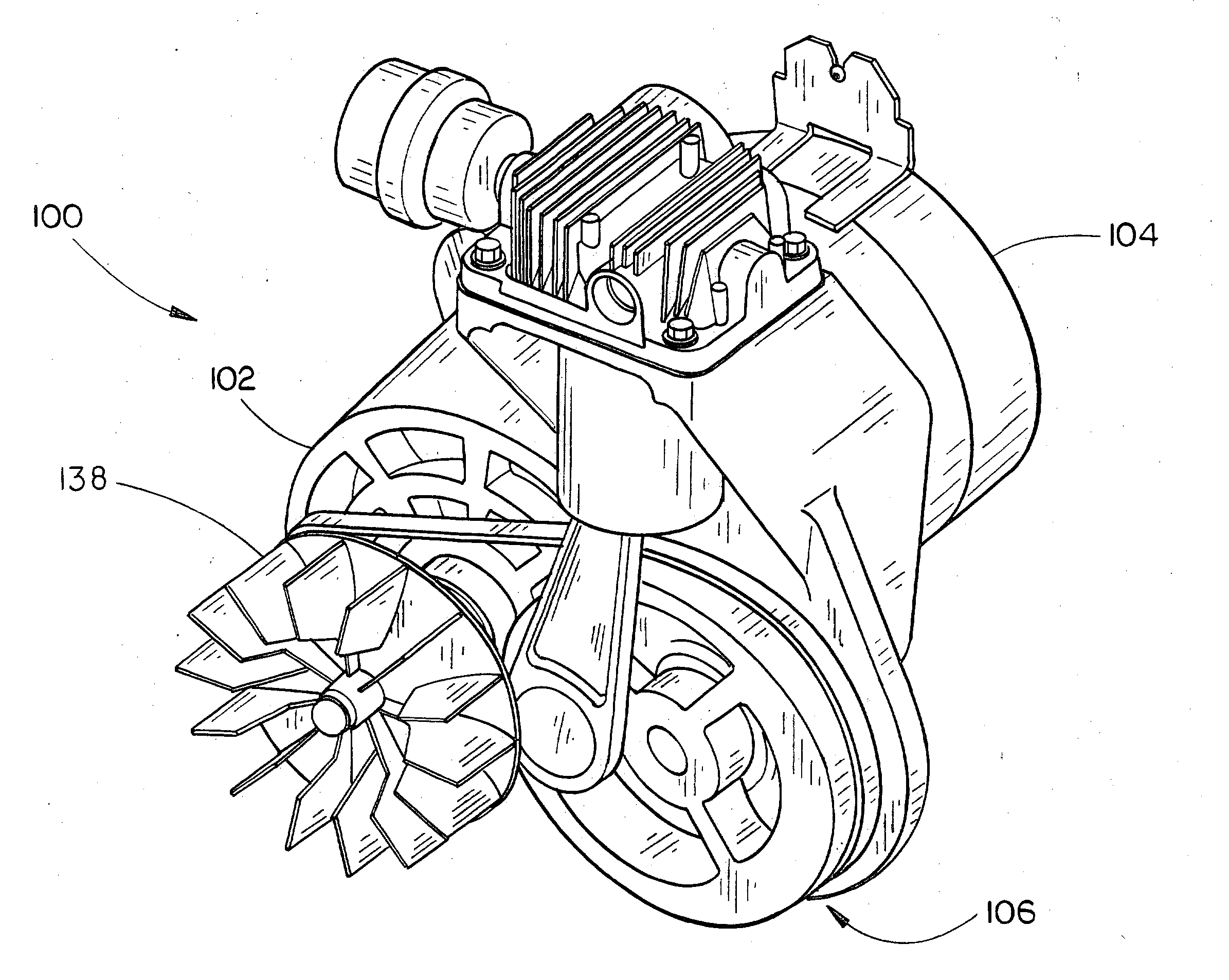
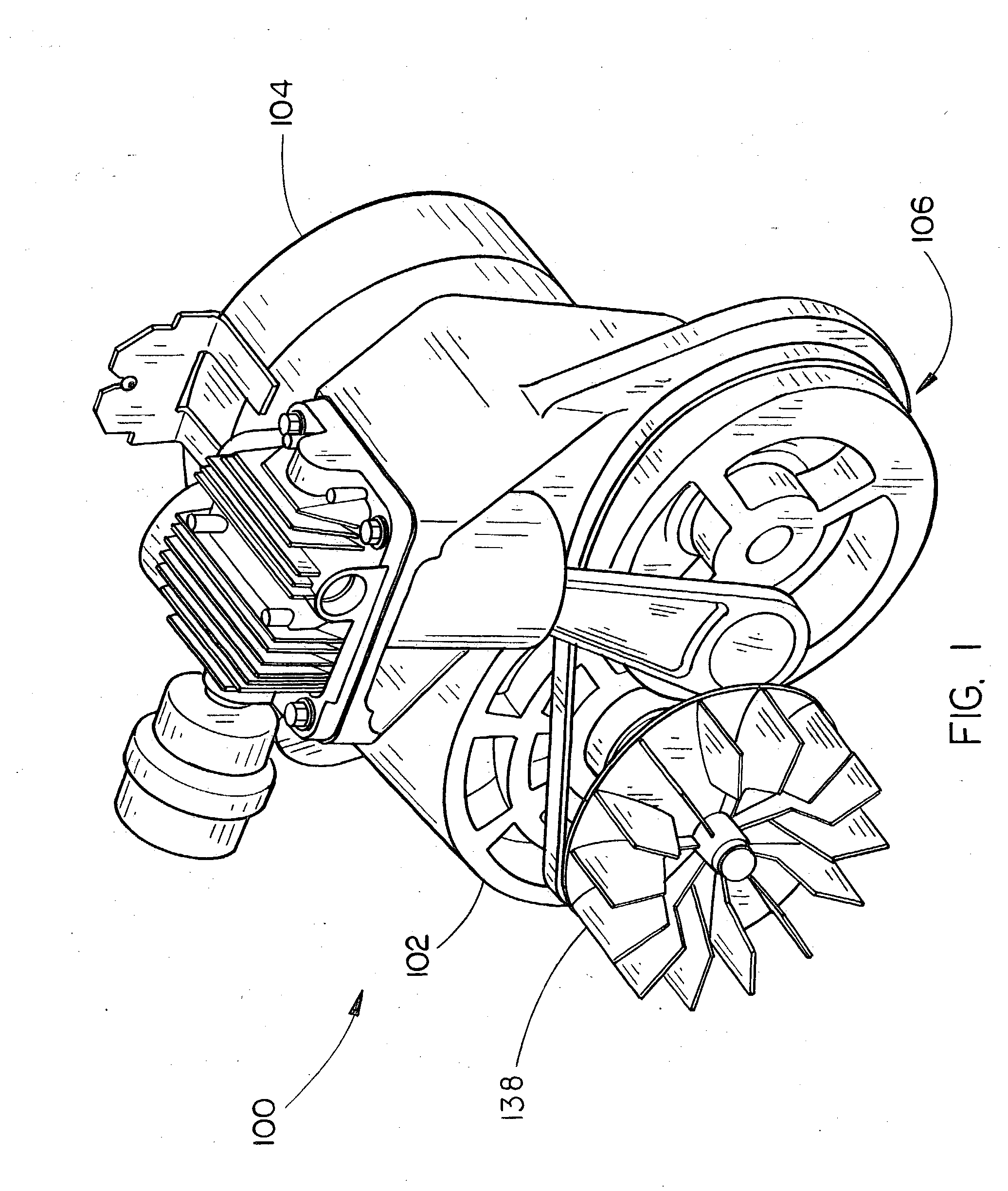
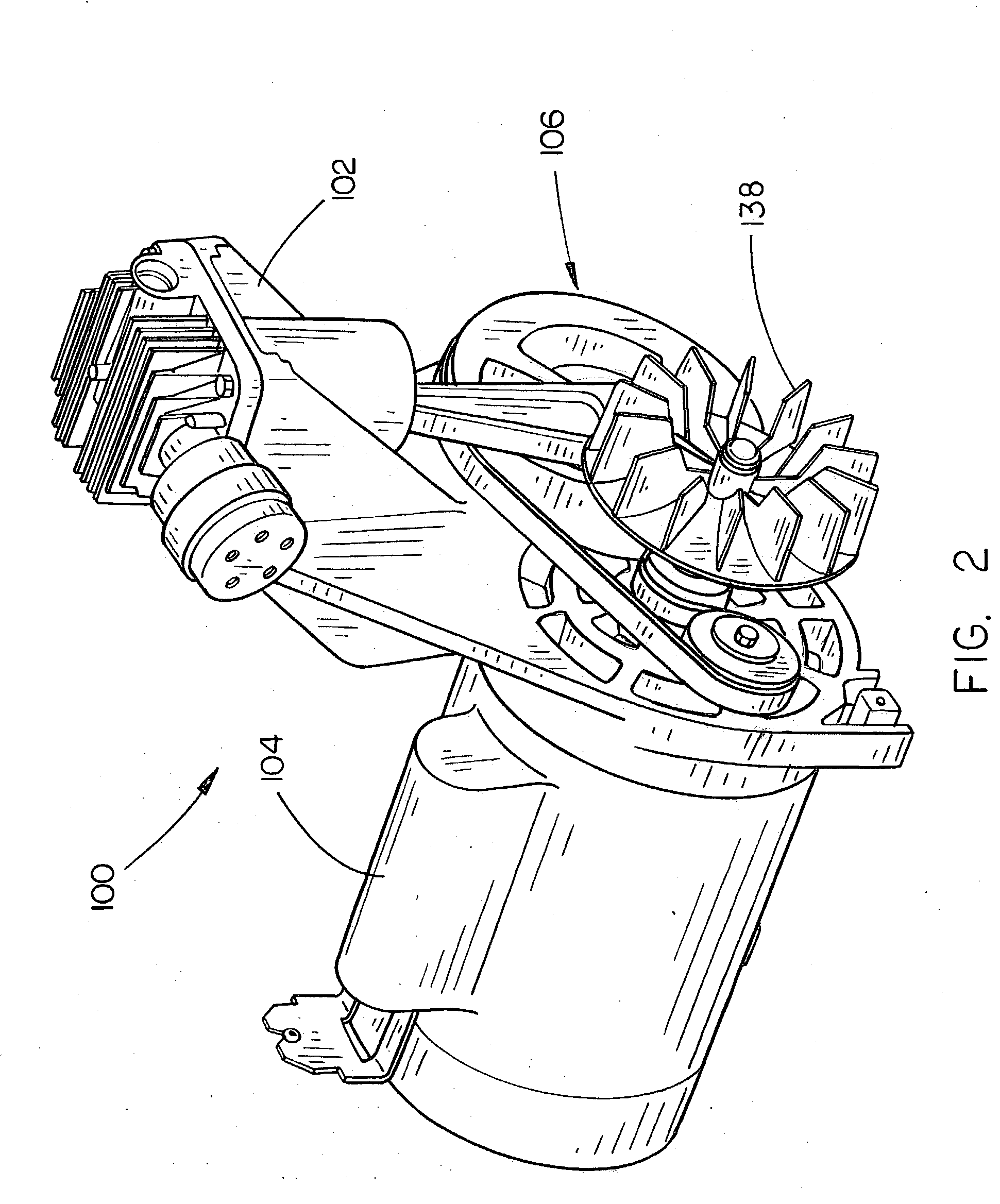
[0017] Referring generally FIGS. 1 through 6, a compressor assembly 100 in accordance with an exemplary embodiment of the present invention is described. The compressor assembly 100 includes a reciprocating piston compressor 102 coupled to a motor assembly (e.g., an electric motor, engine, or the like) 104 via a belt drive 106. In the embodiment illustrated, the compressor 102 includes a compressor housing 108 having a cylinder assembly 110 in which a piston 112 is reciprocated for compressing a gas such as air, or the like. The compressor 102 further includes a head assembly 114 having a valve plate 116 mounted to a boss 118 formed in the compressor housing 108 enclosing the cylinder assembly 110. The head assembly 114 supplies atmospheric air (air at atmospheric pressure) to the cylinder assembly 110 and delivers press...


PUM


Abstract

A compressor assembly includes a compressor coupled to a motor via a belt drive. The belt drive provides a speed reduction between the motor and compressor and causes the compressor shaft to rotate in the direction opposite that of the motor shaft. The relative values of the mass moments of inertia about the axes of rotation of the rotating motor and compressor shafts are engineered to be inversely proportional to the relative shaft speeds, allowing the mass moments of inertia to be balanced to at least substantially eliminate torsional vibration.

Description

CROSS-REFERENCE TO RELATED APPLICATIONS [0001] The present application claims the benefit under 35 U.S.C. § 119(e) of U.S. Provisional Patent Application Ser. No. 60 / 382,123 filed May 21, 2002. Said U.S. Provisional Patent Application Ser. No. 60 / 382,123 is herein incorporated by reference in its entirety.FIELD OF THE INVENTION [0002] The present invention generally relates to compressor assemblies, and, more particularly, to a compressor assembly having counter rotating motor and compressor shafts. BACKGROUND OF THE INVENTION [0003] Traditional positive displacement (reciprocating piston) compressor assemblies include a compressor coupled to a motor using belt drive or direct drive mechanisms which transfer power from the motor to the compressor for reciprocating the piston (or pistons) of the compressor. Conventionally, in such belt drive and direct drive configurations, the drive shaft of the motor (herein after referred to as the motor shaft) and the crank shaft of the compresso...

Claims


Application Information

Patent Timeline
Patent Type & Authority Applications(United States)
IPC IPC(8): F04B17/00F04B35/00
CPCF04B17/03F04B17/05
Inventor WOOD, MARK W.
Owner BLACK & DECKER INC
Why Eureka
Try Eureka