
Network-controlled feedback for MIMO systems

a network-controlled feedback and mimo technology, applied in diversity/multi-antenna systems, wireless communication, spatial transmit diversity, etc., can solve the problems of affecting the antenna selection, the number and mix of users may affect the antenna selection, and the one antenna configuration that is best for all possible operating conditions

Active Publication Date: 2006-04-13
UNWIRED PLANET
View PDF10 Cites 130 Cited by
  • Summary
  • Abstract
  • Description
  • Claims
  • Application Information

AI Technical Summary

Benefits of technology

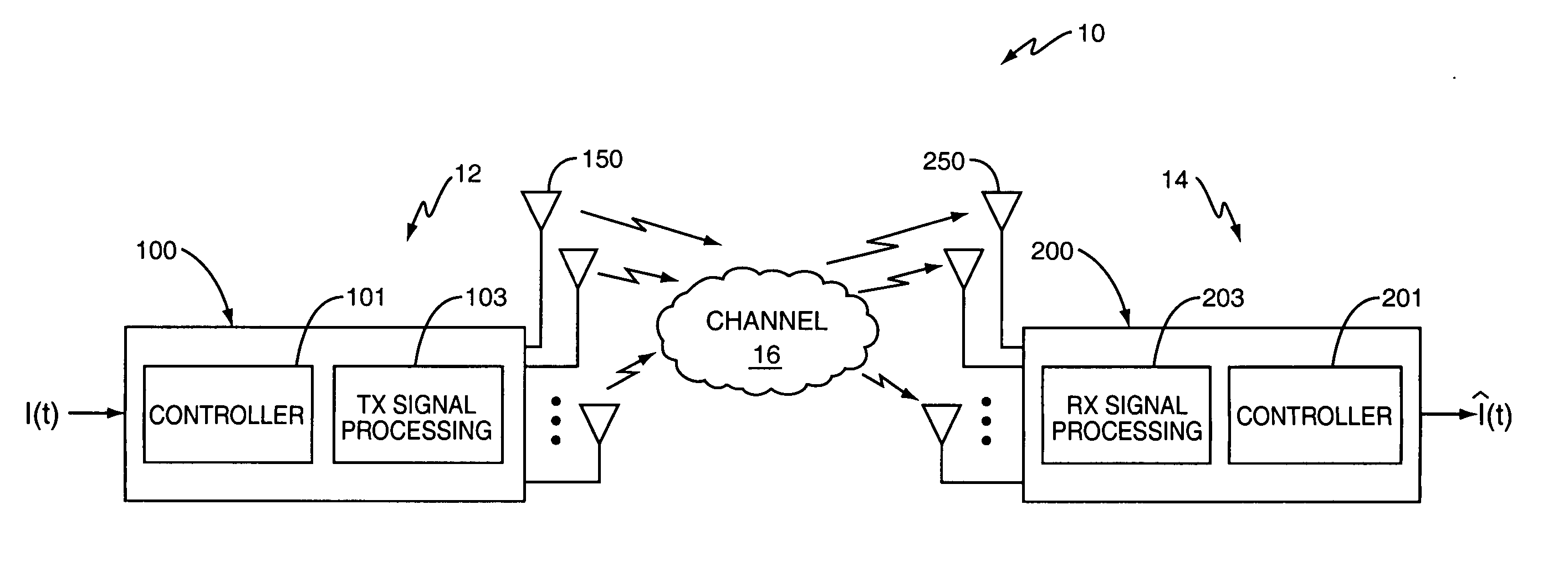
[0008]FIG. 1 illustrates a multiple input, multiple output (MIMO) communication system.

Problems solved by technology

However, there is no one antenna configuration that is best for all possible operating conditions.
Also, the number and mix of users may affect the antenna selection.
Further, only the base station has knowledge of the data queued for each user, which also affects the antenna selection.
When a large number of users are present, the amount of feedback may be excessive and adversely affect the quality and reliability of other uplink channels.

Method used


Image

  • Network-controlled feedback for MIMO systems
  • Network-controlled feedback for MIMO systems
  • Network-controlled feedback for MIMO systems

Examples


second embodiment

[0042]FIG. 6 illustrates an exemplary transmitter 300 based on a spatial multiplexing (SM) architecture. In this embodiment. the input data stream is coded before it is split and the separate bitstreams are then independently modulated and transmitted. The transmitter 300 comprises an encoder 302 to encode the original information stream I(t) to generate a coded bitstream, a demultiplexer 304 to divide the coded bitstream into M bitstreams {b1(t), b2(t), . . . bM(t)}, modulation circuits 306 for each bitstream, and a plurality of transmit antennas 320. The modulation circuit 306 for each bitstream comprises a demultiplexer 308 to divide each coded bitstream into a number of substreams, a plurality of symbol mappers 310 to map each substream to a point on a signaling constellation, a plurality of signal spreaders 312 to apply a selected spreading code to each substream, and a combiner 314 to recombine the substreams to generate a transmit signal {x1(t), x2(t), . . . xM(t)} for trans...

third embodiment

[0043]FIG. 7 illustrates an exemplary transmitter 400 based on a matched field transmit diversity (MFTD) architecture. The input data stream is transmitted from multiple transmit antennas 420 to receiver 200 with one or more receive antennas 250. The input stream is pre-filtered to match the channel between the transmit and receive antennas 420, 250. In this architecture, each stream is transmitted from all transmit antennas 420. The transmission mode corresponds to the number of streams or transmit signals. The pre-filter 412 is used to focus each transmit signal on a selected receive antenna 250.

[0044] The transmitter 400 includes a demultiplexer 402 to divide the information bitstream into a plurality of bitstreams, a coding and modulation circuit 404 for each bitstream, a prefilter 412 matched to the communication channel between the transmitter 400 and the receiver 200, and a plurality of transmit antennas 420. Each coding and modulation circuit 404 includes an encoder 406 to ...


PUM


Abstract

In a selective MIMO system, the mobile station provides channel quality feedback for one or more possible transmission mode. The mobile station provides channel quality feedback for a first mode regardless of channel conditions and determines whether to provide feedback for one or more additional modes based on current channel conditions.

Description

[0001] This application is a continuation-in-part claiming priority from U.S. patent application Ser. No. 10 / 747,752 filed 29 Dec. 2003, which is incorporated herein by reference.BACKGROUND OF THE INVENTION [0002] The present invention relates to multiple-input, multiple output (MIMO) communication systems, and more particularly, to a method and apparatus for limiting feedback in MIMO systems. [0003] In recent years, there has been much interest in multiple input, multiple output (MIMO) systems for enhancing data rates in the High Speed Downlink Packet (HSDPA) channel in a WCDMA system. MIMO systems employ multiple antennas at the transmitter and receiver to transmit and receive information. The receiver can exploit the spatial dimensions of the signal at the receiver to achieve higher spectral efficiency and higher data rates without increasing bandwidth. One MIMO architecture that is attracting significant attention is the Per Antenna Rate Control (PARC) architecture. In PARC syst...

Claims


Application Information

Patent Timeline
Patent Type & Authority Applications(United States)
IPC IPC(8): H04Q7/20H04B1/707
CPCH04B1/71072H04B1/712H04B7/04H04B7/06H04B7/0632H04B7/0645H04B7/0689H04B7/0691H04B7/0697H04B7/0891H04L1/06
Inventor GRANT, STEPHEN J.CHENG, JUNG-FUWANG, YI-PIN ERICMOLNAR, KARL J.KRASNY, LEONID
Owner UNWIRED PLANET
Learn More