
Airway tube guiding apparatus

a technology of airway tube and guiding apparatus, which is applied in the field of guiding apparatus, can solve the problems of requiring considerable operator skill, requiring operator to assume unnatural posture, and difficult work, and achieves the effect of improving workability, facilitating observation, and facilitating observation

Inactive Publication Date: 2006-04-13
MACHIDA ENDOSCOPE
View PDF11 Cites 12 Cited by
  • Summary
  • Abstract
  • Description
  • Claims
  • Application Information

AI Technical Summary

Benefits of technology

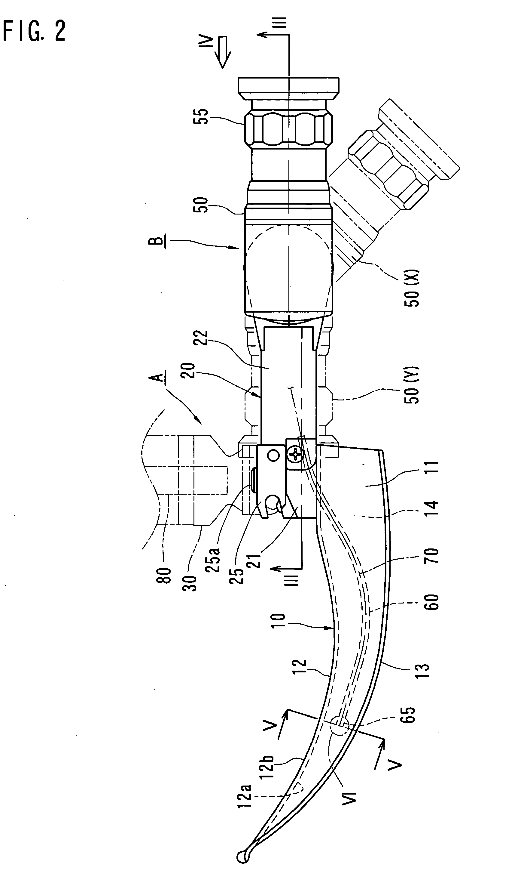
[0009] According to the features of the present invention, an operator can assume a natural posture when inserting the blade and the tube while observing them through the ocular end portion of the endoscope because the ocular end portion of the endoscope is disposed behind the blade out of alignment with the blade either to the right or the left, which makes a hand holding the apparatus and a head of the operator out of alignment with each other, thus improving workability.
[0010] Preferably, the body further includes a handle disposed perpendicular to the blade on a rear end portion of the blade and the ocular end portion is arranged out of alignment either to the right or the left with the plane on which the blade and the handle are disposed. This arrangement allows the operator to position the head and the hand holding the handle out of alignment with each other.
[0011] Preferably, the endoscope includes an ocular cylinder, one end portion of which being rotatably connected with the body by an attachment for rotation around a rotation axis orthogonal to the plane on which the blade and the handle are disposed, and the other end portion of which being provided as the ocular end portion. This arrangement enables the operator to move the ocular end portion to a desired angle position, making observation easier. This arrangement also allows the operator to maintain the ocular end portion at a desired angle position when turning the blade around its rear end portion to depress the epiglottis of the patient, which makes observation all the more easier.
[0012] Preferably, the attachment includes a hollow axial member, the axial member being fixed with either the ocular cylinder or the body and being rotatably supported by the other one, and the image guide is comprised of a bundle of optical fibers, the bundle of optical fibers extending through the ocular cylinder and the axial member of the attachment. This arrangement keeps the image guide from being exposed outside in the vicinity of the ocular cylinder, thus preventing it from disturbing insertion of the blade or the tube.
[0013] Preferably, the blade has a hollow receiving portion formed on it, the receiving portion extending from the rear end portion to an intermediate portion of the blade along the longitudinal direction thereof, the receiving portion being disposed adjacent to the guiding surface, the image guide extending through the receiving portion, the objective end portion of the endoscope being disposed at a window opened at a distal end surface of the receiving portion. This arrangement keeps the image guide from being exposed outside in the vicinity of the blade, thus preventing it from disturbing insertion of the blade or the tube.

Problems solved by technology

The work can be difficult, requiring considerable operator skill.
Such apparatus as those disclosed in the above-mentioned documents, however, tend to oblige the operator to assume an unnatural posture when inserting the blade and the tube while also observing them through the ocular end portion of the endoscope, because the ocular end portion of the endoscope is arranged behind and in alignment with the blade.

Method used


Image

  • Airway tube guiding apparatus
  • Airway tube guiding apparatus
  • Airway tube guiding apparatus

Examples


Embodiment Construction

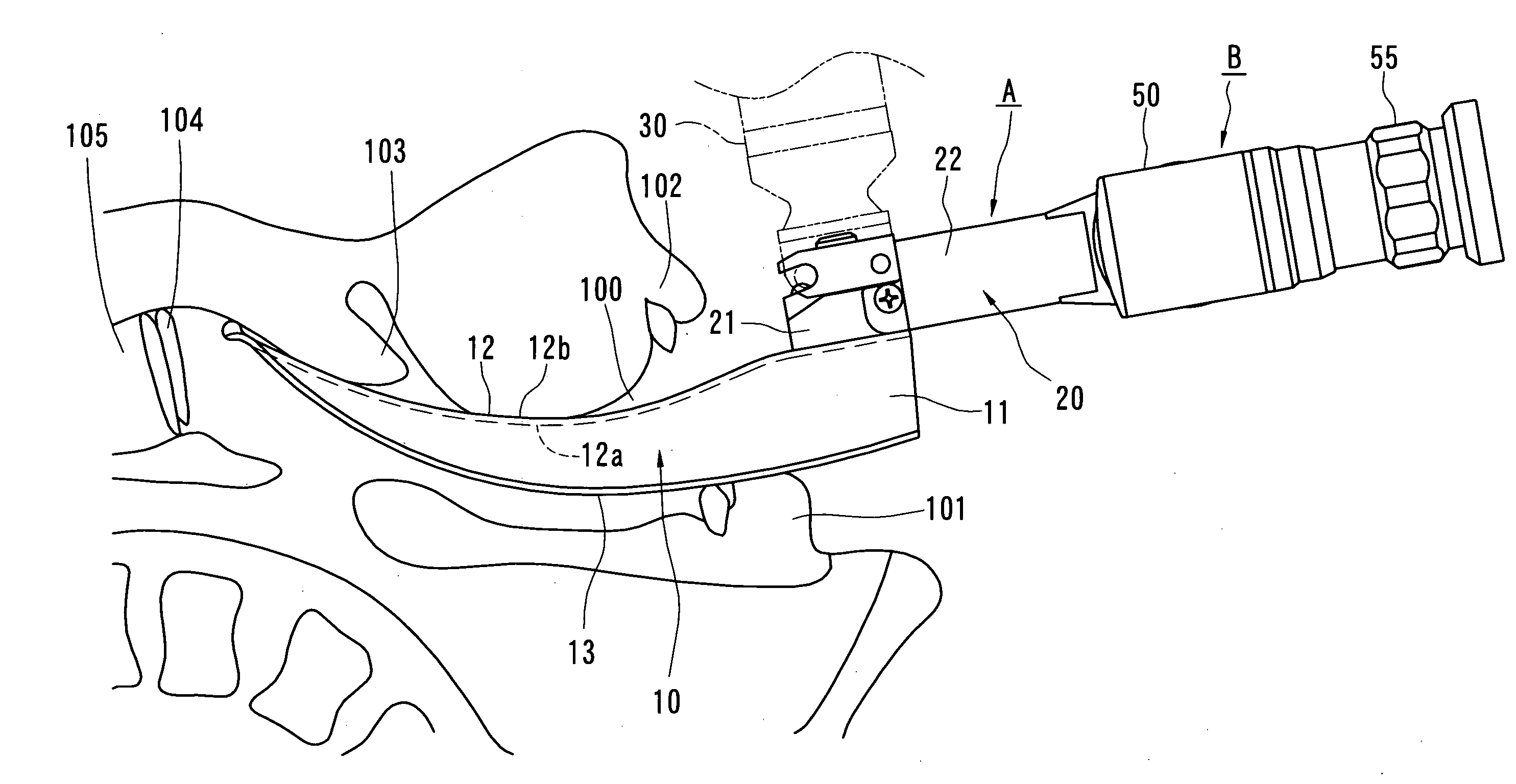
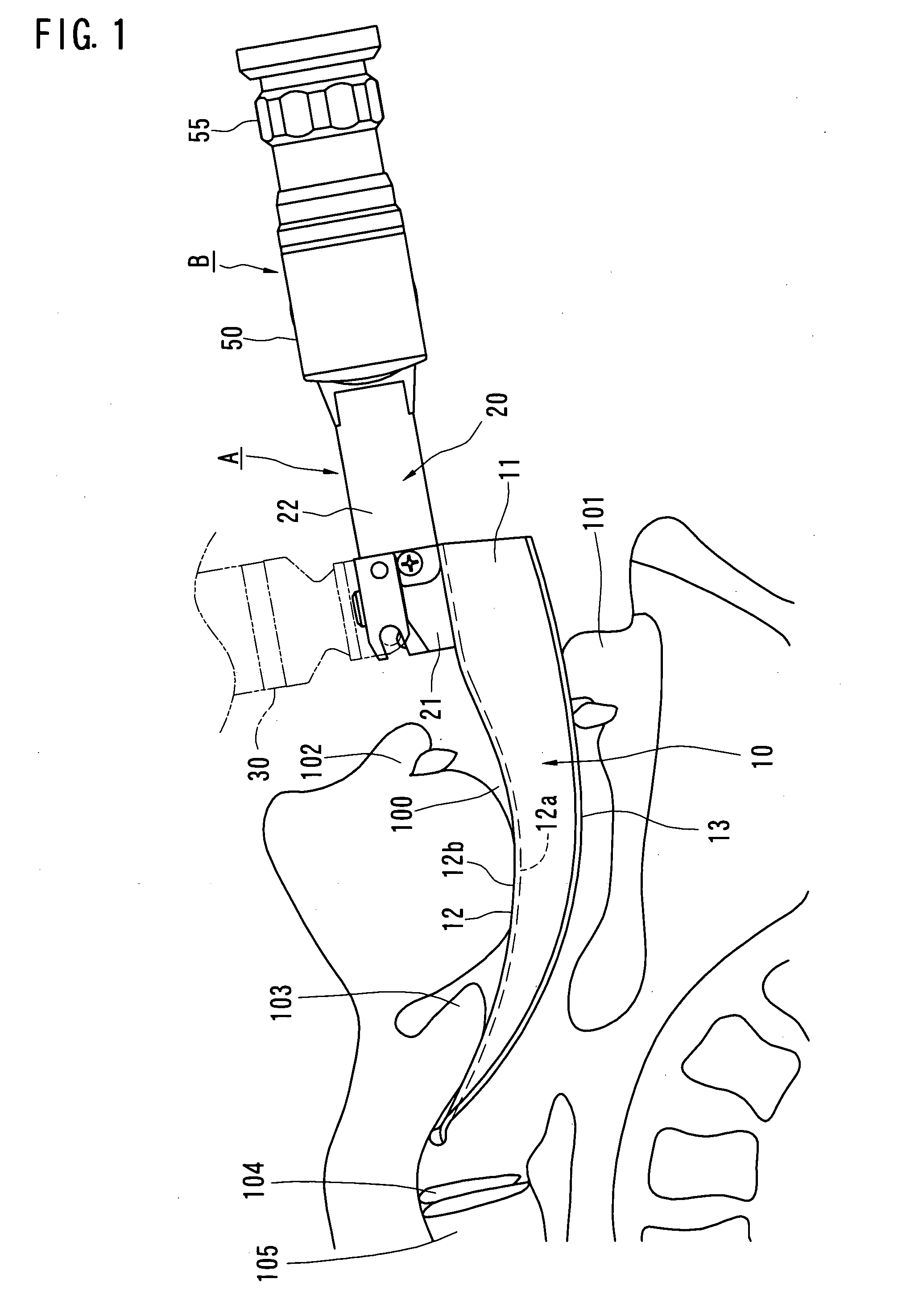
[0020] One preferred embodiment of an airway tube guiding apparatus according to the present invention will be described hereinafter with reference to the accompanying drawings. As shown in FIGS. 1 and 2, the guiding apparatus comprises a body A and an endoscope B. The body A includes a blade 10, a base 20 fixed on the rear end portion of the blade 10 and a handle 30 fixed on the base 20.

[0021] The blade 10 has a curved and tapered shape when viewed from a side as shown in FIGS. 1 and 2, and a generally Z-shaped cross section as shown in FIG. 5, and includes a flat plate-shaped main wall 11, a guiding wall 12 extending from one edge (an upper edge in an in-use condition) of the main wall 11 in a direction perpendicular to the main wall 11, and an abutment wall 13 extending from the other edge (a lower edge in an in-use condition) of the main wall 11 in a direction perpendicular to the main wall 11. The guiding wall 12 and the abutment wall 13 extend in opposite directions from each...


PUM


Abstract

A guiding apparatus to be used when inserting an airway tube from a mouth of a patient includes a body (A) and an endoscope (B) disposed through the body (A). The body (A) includes a blade (10). The blade (10) is inserted from the mouth of the patient to depress the epiglottis with a distal end portion thereof, exposing the glottis. The endoscope (B) includes an objective end portion (65), an ocular end portion (55) and an image guide (70) optically connecting the objective end portion (65) and the ocular end portion (55). The objective end portion (65) is disposed on the blade (10). The ocular end portion (55) is positioned out of alignment with the blade (10) either to the right or the left behind a rear end of the blade (10).

Description

BACKGROUND OF THE INVENTION [0001] 1. Field of the Invention [0002] This invention relates to a guiding apparatus to be used when inserting an airway tube into a patient's trachea. [0003] 2. Description of Related Art [0004] It is a known practice to insert an airway tube (endotracheal tube) into a trachea of a patient who had his or her airway obstructed in an emergency such as a traffic accident to open and maintain an airway, and to supply oxygen if needed. To help insert the tube, a guiding apparatus with a blade is commonly used. The blade is inserted into the mouth of the patient to depress the epiglottis with its distal end portion exposing the glottis. Then the tube is inserted from the mouth into the trachea, guided along the blade in the longitudinal direction. [0005] Usually, an operator inserts the blade and the tube observing the throat, the epiglottis and the glottis of the patient while also illuminating them with illumination light from outside. The work can be diffi...

Claims


Application Information

Patent Timeline
Patent Type & Authority Applications(United States)
IPC IPC(8): A61B1/00
CPCA61B1/06A61B1/267A61M16/0488
Inventor MIYAGI, KUNIHIKO
Owner MACHIDA ENDOSCOPE
Learn More