Eureka AIR delivers breakthrough ideas for toughest innovation challenges, trusted by R&D personnel around the world.

Fluid flow rate sensor and method of operation

Inactive Publication Date: 2006-04-13
THERM O DISC
View PDF9 Cites 17 Cited by
  • Summary
  • Abstract
  • Description
  • Claims
  • Application Information

AI Technical Summary

Benefits of technology

[0014] As a thermo-anemometer-type sensor, the fluid flow rate sensor of the invention does not incorporate any moving parts. The design of the sensor of the invention and its method for operation results in the sensor having a faster response time than prior known fluid flow rate sensors making it suitable for many sensing applications not before available to thermo-anemometer-type fluid flow rate sensors. The fluid flow rate sensor of the invention may be easily integrated into a variety of fluid delivery systems.

Problems solved by technology

All too often, however, the fluid delivery systems are susceptible to fluctuations in the fluid line pressure, and resultantly, the fluid flow rate varies.
In such instances, when the fluid line pressure is lower than expected, an under-fill condition typically occurs.
Conversely, when the fluid line pressure is greater than expected, an over-fill condition may result.
This is because there exists the probability that contaminants, debris or other small particle matter may be present in the fluid.
Such flow rate sensors, though well-known, have traditionally lacked the necessary response times to make them suitable for many common applications, like water delivery systems for household appliances.
This method, however, can take a relatively long time period to provide usable results.
In some applications, however, such as in an icemaker, for example, this response time is much too slow.

Method used


Image

  • Fluid flow rate sensor and method of operation
  • Fluid flow rate sensor and method of operation
  • Fluid flow rate sensor and method of operation

Examples


Embodiment Construction

[0032] The following description of the preferred embodiments is merely exemplary in nature and is in no way intended to limit the invention, its application, or uses.

[0033] The present invention provides an improved fluid flow rate sensor and associated method for operation improving the valid detection response time of the sensor and being capable of easy integration into a variety of fluid delivery or monitoring systems.

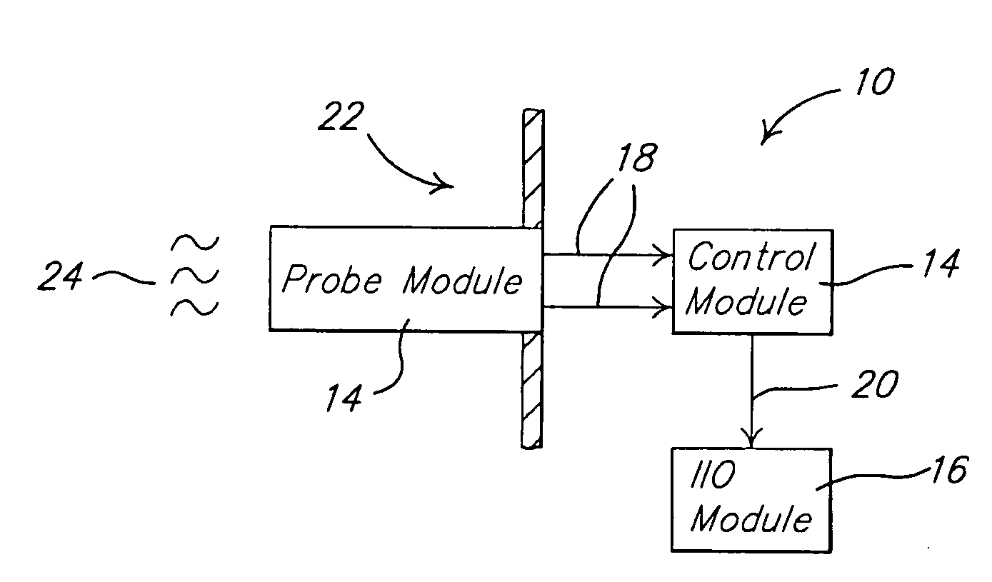
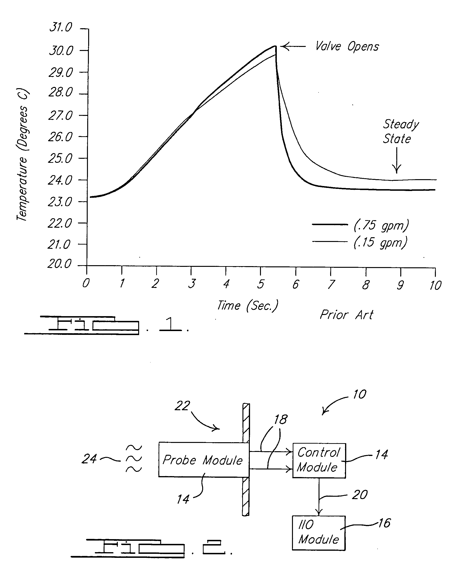
[0034]FIG. 2 generally depicts the major components of the fluid flow rate sensor 10 of the invention. The sensor 10 generally includes a probe 12 coupled with a control module 14. An I / O module 16 may also be included in the sensor 10. As used in this description, the term module refers to an application specific integrated circuit (ASIC), an electronic circuit, a processor (shared, dedicated, or group) and memory that execute one or more software or firmware programs, a combinational logic circuit, and / or other suitable components that provide the described fu...


PUM


Abstract

A thermo-anemometer-type fluid flow rate sensor design and a method for its operation that overcome the response time limitations of prior known fluid flow rate sensors is disclosed. The fluid flow rate sensor comprises a probe having a detection module adapted to change condition in response to the presence of the flow of the fluid, a control module that is electrically connected to the probe that monitors the condition of the detection module over time (e.g., a temperature), determines a rate of change of that condition over time, and generates an output that is indicative of the rate of flow of the fluid, and a I / O module connected to the control module to provide a means for communicating the output of the control module to another device or a user.

Description

FIELD OF THE INVENTION [0001] The present invention generally relates to a fluid flow rate sensor and method for its operation. BACKGROUND OF THE INVENTION [0002] Fluid delivery systems have a wide variety of applications and are commonplace in many household appliances, such as metered water dispensers, icemakers, dishwashers, and clothes washers. In such systems, the volume of the fluid to be dispensed is typically controlled by a timing mechanism operable to open and then close a valve after predetermined period of time has elapsed. [0003] These fluid delivery systems operate under the presumed condition that the fluid line pressure and, correspondingly, the fluid flow rate are known and static. All too often, however, the fluid delivery systems are susceptible to fluctuations in the fluid line pressure, and resultantly, the fluid flow rate varies. In such instances, when the fluid line pressure is lower than expected, an under-fill condition typically occurs. Conversely, when th...

Claims


Application Information

Patent Timeline
IPC IPC(8): G01F1/00
CPCG01F1/696G01F1/698G01F1/72G01F1/6986
Inventor ZIMMERMANN, BERND D.YANG, TUNG-SHENGBOSTIC, LANCE A.
Owner THERM O DISC
Why Eureka
Eureka Blog
Learn More