Ultrasonic placement and monitoring of an endotracheal tube

a technology of endotracheal tube and ultrasonic placement, which is applied in the field of medical devices, can solve the problems of barotrauma and hypotension, atelectasis of the unventilated lung, and the placement and monitoring of the ett within the body remains a significant obstacle,

Inactive Publication Date: 2006-04-20
PLASIATEK
View PDF26 Cites 63 Cited by
  • Summary
  • Abstract
  • Description
  • Claims
  • Application Information

AI Technical Summary

Problems solved by technology

The placement and monitoring of the ETT within the body remains a significant obstacle in endotracheal intubation procedures.
Malpositioning may result when the ETT is inadvertently placed into the esophagus tube, causing air to be injected into the stomach instead of the trachea.
In certain circumstances, the lung that is being improperly ventilated may become hyperventilated due to the higher concentrations of inspired oxygen, causing barotraumas and hypotension.
Atelectasis of the unventilated lung may also result from the improper insertion of the ETT into the bronchi.
Flexion or extension of the patient's neck can change the desired positioning of the ETT, in some cases resulting in extubation from the trachea.
In addition, mucus, blood, or other biological materials may also result in the movement or blockage of the ETT, requiring further action by the caregiver to ensure proper ventilation of the patient.
In any of these scenarios, the lack of proper ventilation within the patient may lead to cardiac arrest or irreversible central nervous system damage within a relatively short period of time.
Anatomical variations from patient to patient can, however, re

Method used


Image

  • Ultrasonic placement and monitoring of an endotracheal tube
  • Ultrasonic placement and monitoring of an endotracheal tube
  • Ultrasonic placement and monitoring of an endotracheal tube

Examples


Embodiment Construction

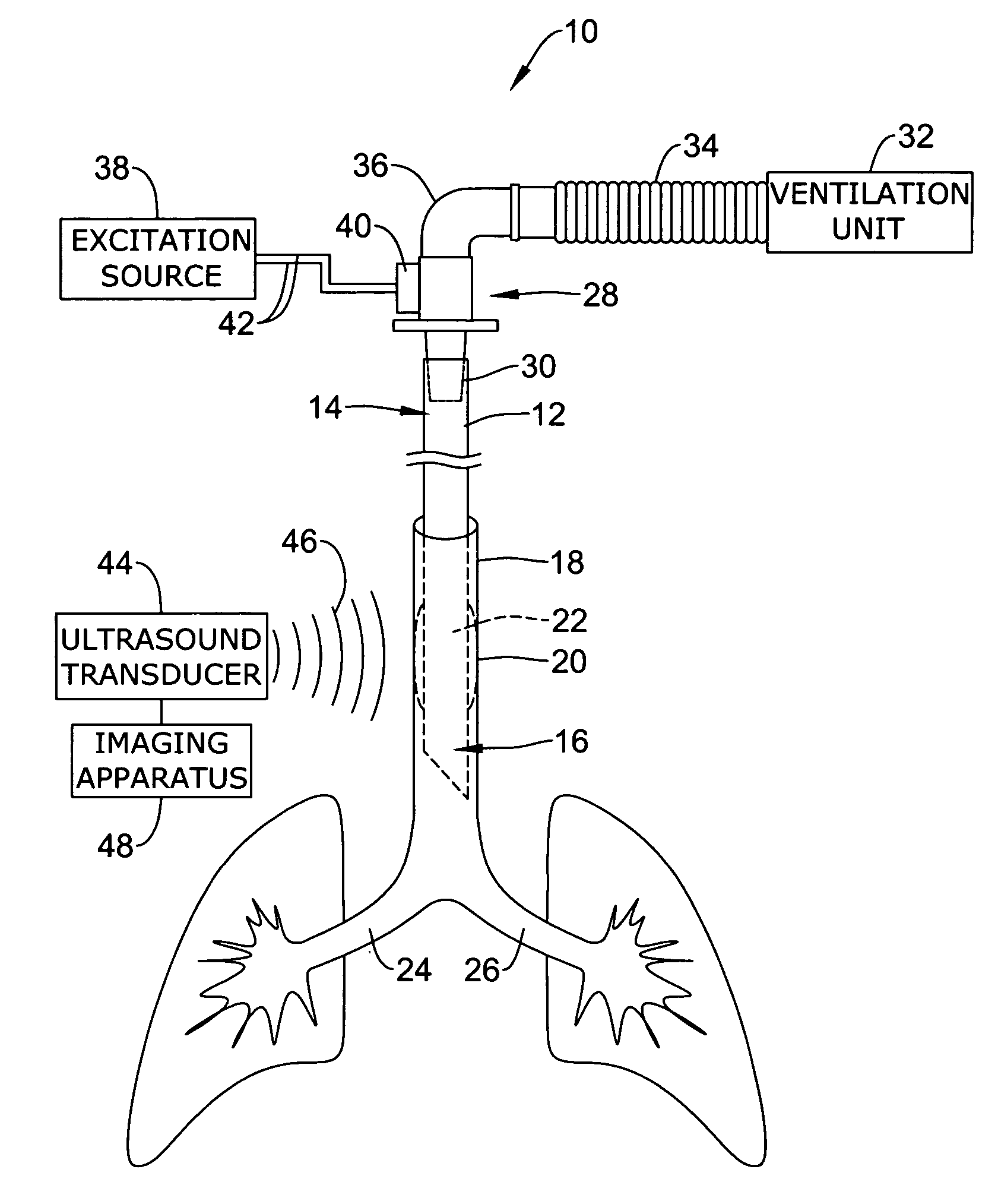
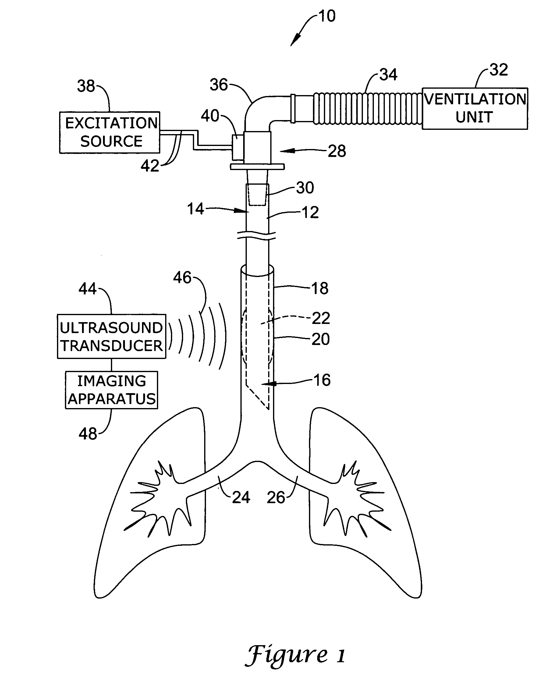
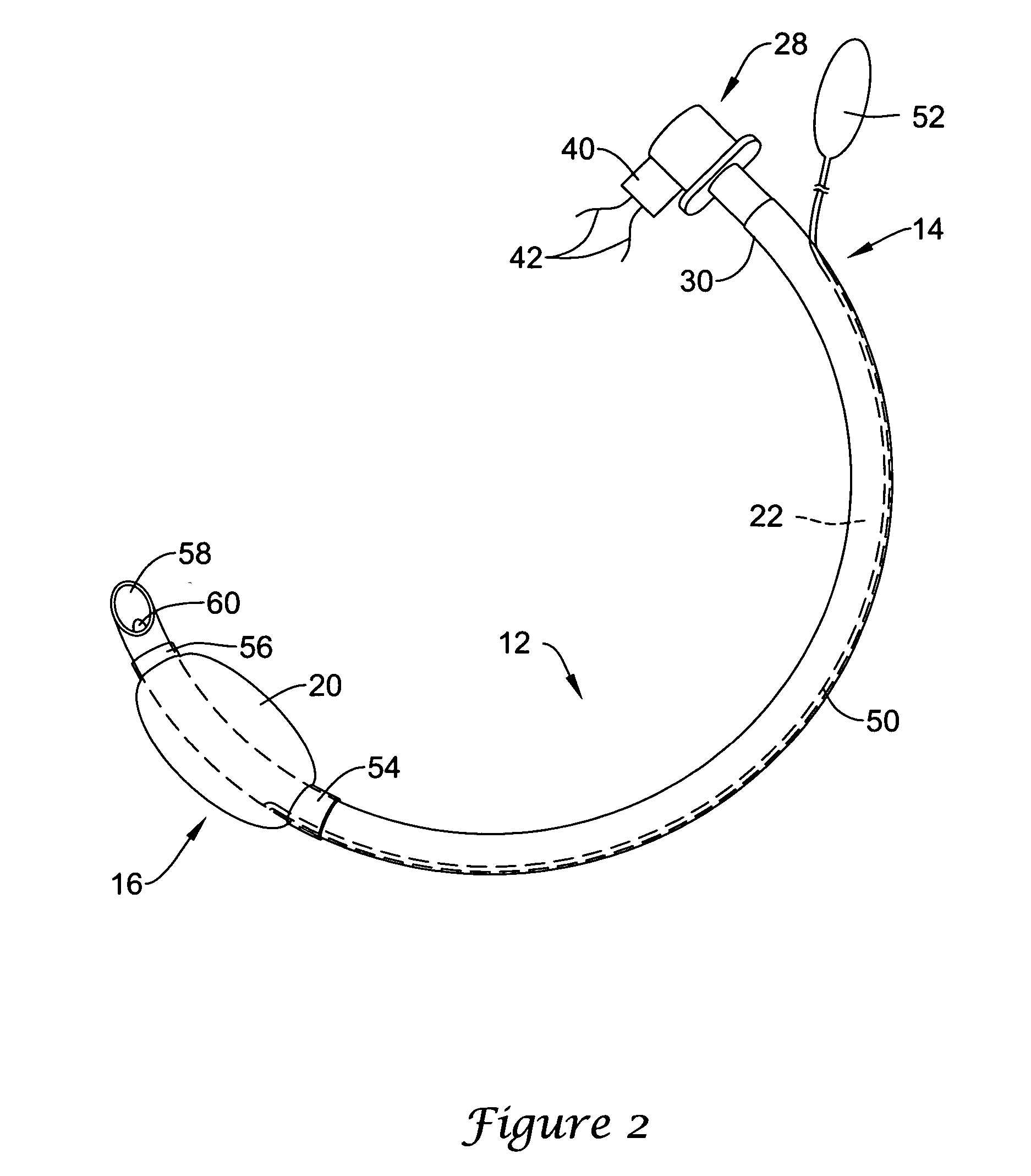
[0024] The following description should be read with reference to the drawings, in which like elements in different drawings are numbered in like fashion. The drawings, which are not necessarily to scale, depict selected embodiments and are not intended to limit the scope of the invention. Although examples of construction, dimensions, and materials are illustrated for the various elements, those skilled in the art will recognize that many of the examples provided have suitable alternatives that may be utilized.

[0025]FIG. 1 is a diagrammatic view of an illustrative system 10 for ultrasonically monitoring the placement of an endotracheal tube (ETT) 12 within the body. As shown in FIG. 1, the endotracheal tube 12 can include a proximal section 14 that can be manipulated from a position outside of a patient's body during the intubation procedure, and a distal section 16 that can be advanced within the patient's airway to a desired location within the trachea 18. As is discussed in gre...


PUM


Abstract

A system for ultrasonically placing and monitoring an endotracheal tube within a patient. The system includes an endotracheal tube having a proximal and a distal end and a ventilation lumen disposed there through. A vibration mechanism is coupled to the endotracheal tube. One ultrasonic transducer is located outside the patient's body. An ultrasonic imaging apparatus is coupled to the ultrasonic transducer for digitalizing the endotracheal tube within the body.

Description

[0001] This application claims the benefit of U.S. Provisional Application No. 60 / 559,325 as filed on Apr. 2, 2004.FIELD OF THE INVENTION [0002] The present invention relates generally to the field of medical devices. More specifically, the present invention pertains to systems and methods for ultrasonic placement and monitoring of an endotracheal tube within the body. BACKGROUND OF THE INVENTION [0003] A number of medical procedures require the insertion of a tube, catheter, cannula, or other similar device into the body. Such devices are used, for example, in the fields of anesthesiology, cardiology, endoscopy, urology, laparoscopy, and vascular therapy to deliver fluids such as oxygen and anesthetics to targeted regions within the body. In the field of anesthesiology and critical care, for example, it may be necessary to deliver air / oxygen to the anesthetized patient using an endotracheal tube (ETT). Such tubes are routine used in the clinical, ICU, emergency room, and pre-hospit...

Claims


Application Information

Patent Timeline
IPC IPC(8): A62B9/06A61M16/00A61B8/08A61M16/04
CPCA61B8/0833A61B8/0841A61M16/04A61M16/0411A61M16/0488A61M2205/3375A61M16/0434A61M16/042A61M16/0438A61M16/0484
Inventor MILLER, MICHAELHOVLAND, CLAIRE T.
Owner PLASIATEK
Why Eureka
Try Eureka