
Magnetic particle flow detector

a detector and magnetic material technology, applied in the field of small magnetic material particles or magnetizable beads, can solve the problems of drastically different magnetic field disruptions or anomalies, difficult to detect individual magnetic material particles in microfluidic flow streams,

Active Publication Date: 2006-04-20
NVE CORP
View PDF27 Cites 52 Cited by
  • Summary
  • Abstract
  • Description
  • Claims
  • Application Information

AI Technical Summary

Benefits of technology

"The present invention is a system for detecting magnetic fields using a thin film made of a material that has strong magnetic properties. The system includes a substrate with a magnetic field sensor placed on it. A layer of material is placed on top of the substrate, creating a gap between the substrate and the layer of material. The gap is extended in two directions, allowing for a larger area of interaction between the substrate and the layer of material. The system also includes two electrical conductors, one on the substrate and in direct contact with the magnetic field sensor, and another in a separate region of the layer of material. The technical effect of this invention is to provide a more efficient and accurate system for detecting magnetic fields."

Problems solved by technology

Detecting individual magnetic material particles in microfluidic flow streams is difficult in many such situations.
A significant difficulty in extending such detection technology to the detection of individual ones of the magnetic material particles in such flows is that a single particle is not necessarily confined to a specific location in the cross section of a microfluidic channel during such flow of the ferrofluids.
This lack of certainty in position in the flow channel leads to drastically different magnetic field disruptions or anomalies (magnetic intensity vs. time) due to those otherwise substantially identical particles passing by the magnetic field detector.

Method used


Image

  • Magnetic particle flow detector
  • Magnetic particle flow detector
  • Magnetic particle flow detector

Examples


Embodiment Construction

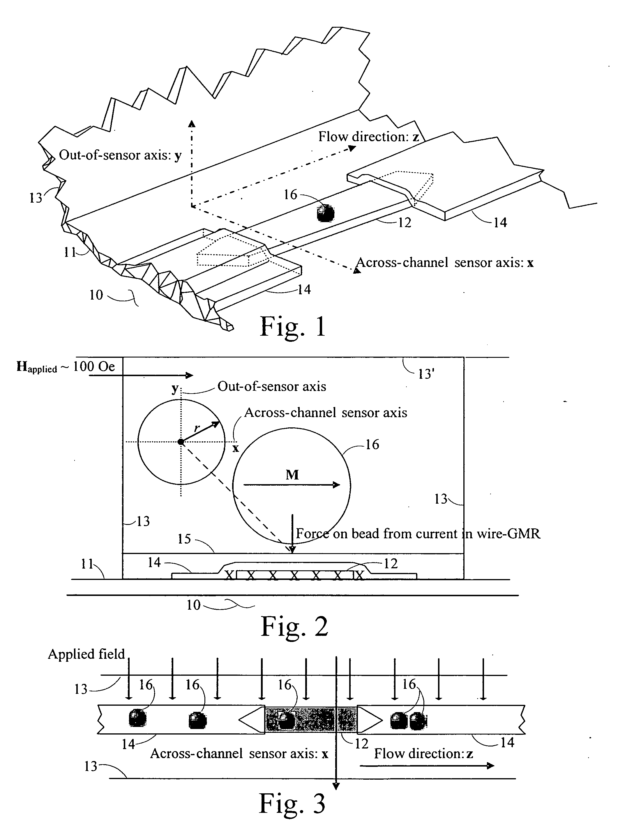
[0038] Detection of individual magnetic material particles in a liquid flow entraining to them to some extent is not so difficult for many larger size magnetic material particles (Dynal 2.8 mm diameter particles, for instance) because the intrinsic signal to noise ratio is very large. As such particles get smaller, however, the detection problem becomes more difficult.

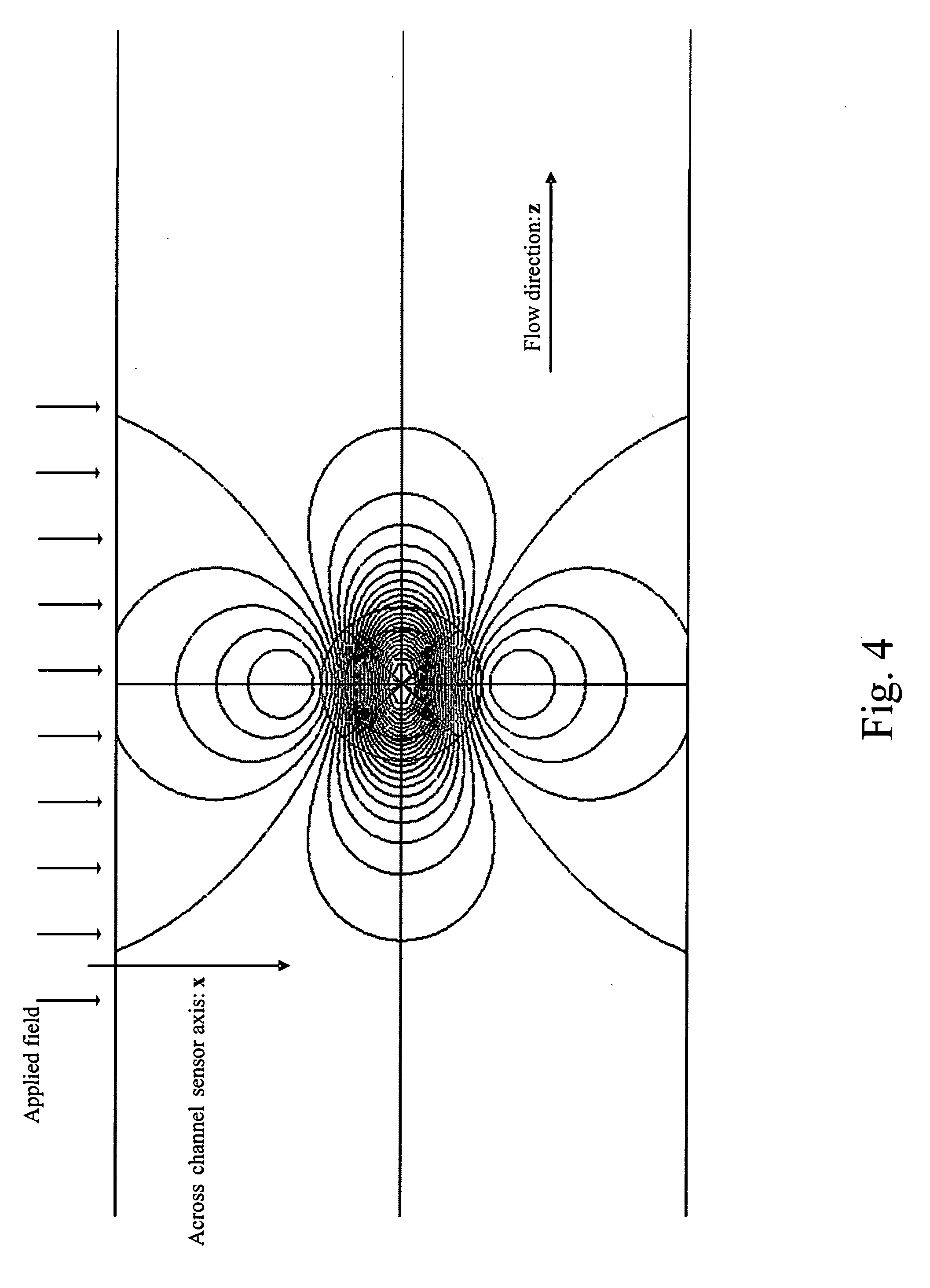
[0039] Confining small magnetic material particles entrained to an extent in a liquid flow to specific parts of the cross section of the flow channel so as to pass a particle detector, however, greatly enhances the detectability of single ones of multiple particles in such flows. Furthermore, confining particles to that part of the cross section of the flow channel that is nearest to the magnetic field detector increases the magnitude at that detector of the magnetic field disruptions that result from the passage thereby of single ones of the multiple particles in the flow.

[0040] Controlling both the flow speed and t...


PUM


Abstract

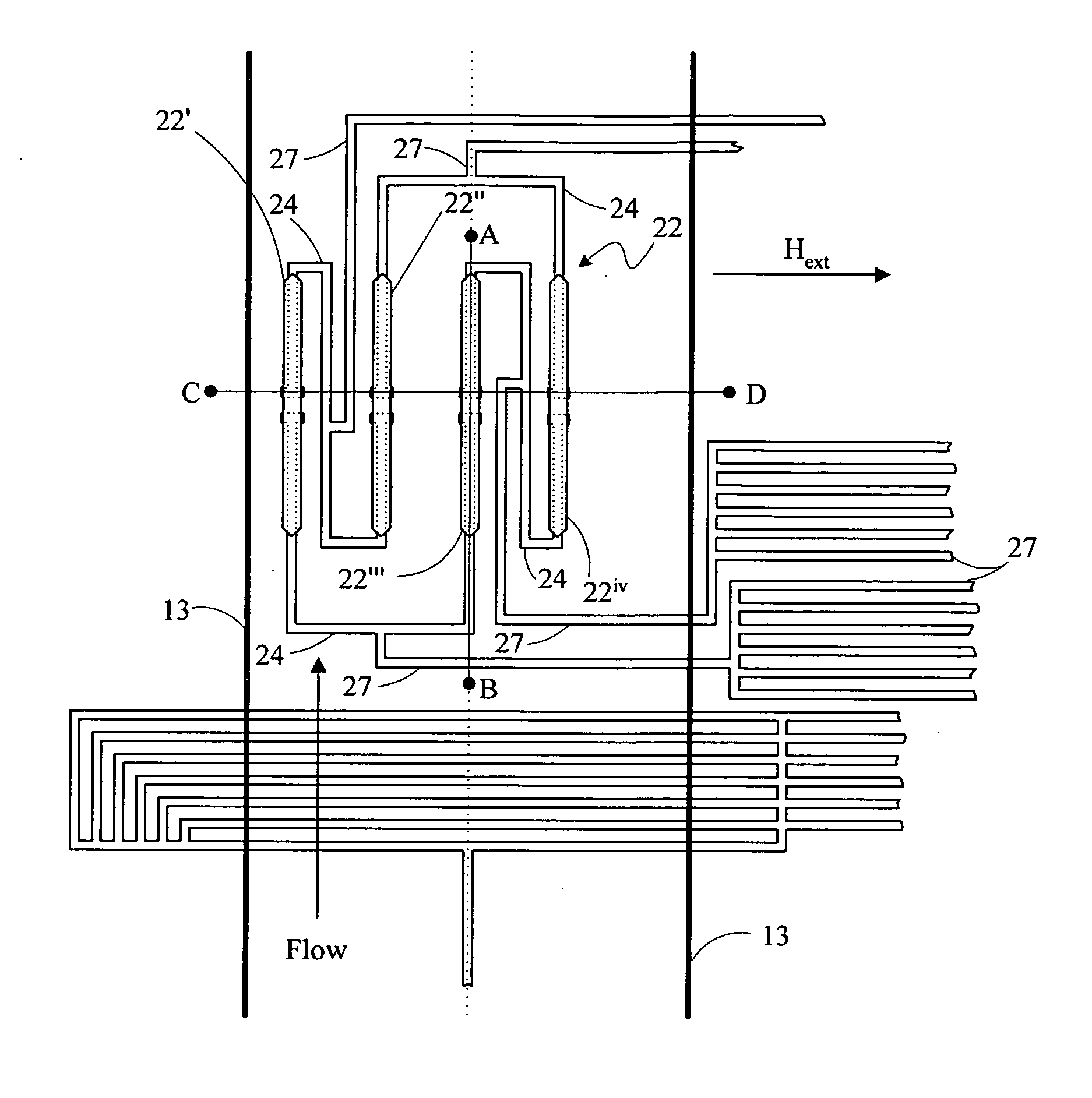
A ferromagnetic thin-film based magnetic field detection system having a substrate supporting a magnetic field sensor in a channel with a first electrical conductor supported on the substrate positioned at least in part along the channel gap and in direct contact with at least some surface of the magnetic field sensor ands a second electrical conductor supported on the substrate positioned at least in part along the channel gap in a region thereof adjacent to, but separated from, the magnetic field sensor.

Description

CROSS-REFERENCE TO RELATED APPLICATION [0001] This application claims the benefit of Provisional Application No. 60 / 614,279 filed on Sep. 29, 2004 for “MAGNETIC PARTICLE FLOW DETECTOR”.BACKGROUND OF THE INVENTION [0002] The present invention relates to small magnetic material particles, or magnetizable beads, in fluid flows and, more particularly, to detection of such particles or beads in such flows. [0003] Among the biomolecular detection methods used to detect selected molecules in the presence of other kinds of molecules mixed therewith are binding assays which are based on use of certain binding molecules to capture through specific chemical bondings the molecules selected for detection. Such specific bondings include polynucleic acid bondings or hybridizations involving DNA and RNA, antibody to antigen bondings, and various ligand to various receptor bondings. The detection of the selected molecules may be of primary interest in its own right, but may instead be of primary int...

Claims


Application Information

Patent Timeline
Patent Type & Authority Applications(United States)
IPC IPC(8): H01L43/00
CPCG01R33/1276G01V3/08Y10S977/932Y10S977/933Y10S977/934
Inventor TONDRA, MARK C.ANDERSON, JOHN M.BROWNELL, DAVID J.POPPLE, ANTHONY D.
Owner NVE CORP
Learn More