Tool positioning device and machining tool

Active Publication Date: 2006-04-20
HITACHI SEIKO LTD
View PDF35 Cites 3 Cited by
  • Summary
  • Abstract
  • Description
  • Claims
  • Application Information

AI Technical Summary

Benefits of technology

[0025] The invention described above allows a standard tool to be used and a life of the tool to be prolonged, so that the running cost may be reduced. Still more, the invention requires no change in the structure of a printed board machining apparatus, so that it is applicable to the conventional printed board machining apparatus.
[0026] Still more, because the inventive device is provided with the concave portion, it requires no positioning of a channe

Problems solved by technology

However, because the channel is provided on the shank portion in the both conventional technologies disclosed in Japanese Publication Patent No. 2894924 and Japanese Patent Laid-Open No. 2002-337016, a unit cost of thei

Method used


Image

  • Tool positioning device and machining tool
  • Tool positioning device and machining tool
  • Tool positioning device and machining tool

Examples


Embodiment Construction

[0036] The invention will now be described based on preferred embodiments, which do not intend to limit the scope of the invention, but exemplify the invention. All of the features and the combinations thereof described in the embodiments are not necessarily essential to the invention.

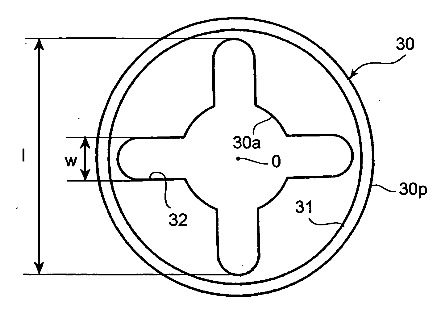
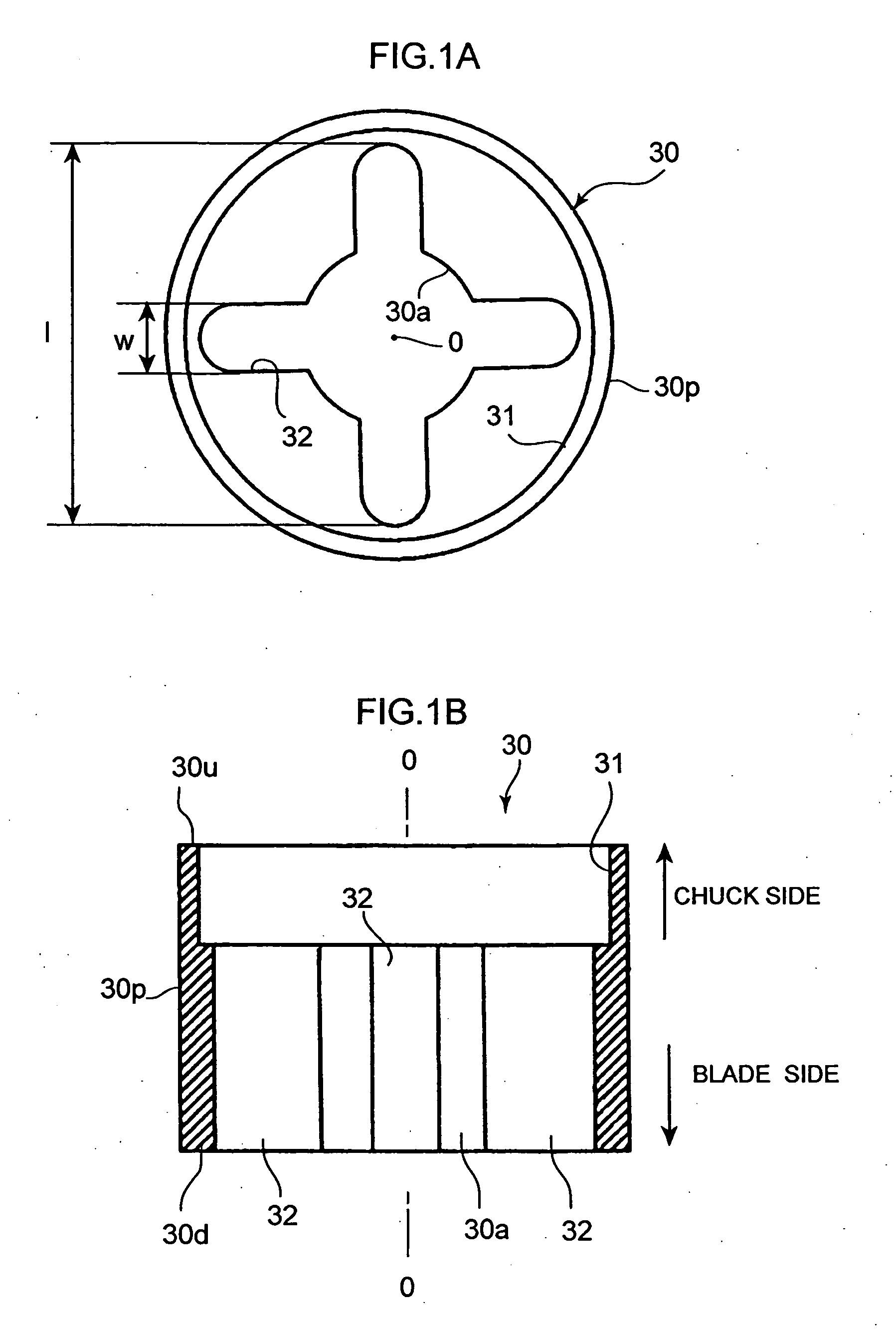
[0037]FIGS. 1A and 1B show an inventive ring, wherein FIG. 1A is a plan view thereof and FIG. 1B is a front section view. It is noted that parts therein which are the same or have the same function with those shown in FIGS. 4 through 6 will be denoted by the same reference numerals and overlapping explanation thereof will be omitted here.

[0038] The inventive ring (tool positioning device) 30 has a hole 30a that penetrates through a center part of the device in an axial direction (O-O) to attach the tool, an upper face 30u which is a plane orthogonal to the axial direction, a lower face 30d which is a plane orthogonal to the axial direction, an outside face 30p that connects an outer edge of the upper...


PUM


Abstract

There is provided a tool positioning device and a machining element whose structures are simple and which can reduce a running cost. In addition to a hole that engages with a shank of an end mill, a channel is provided so that it penetrates through the device such that one end thereof communicates with an upper face of the device and the other end communicates with a lower end of the device. In this case, it is more effective to provide a concave portion that is opened to the upper face and communicates with the hole. The same effect may be obtained by making a cylindrical hole for example instead of the channel.

Description

FIELD OF THE INVENTION [0001] The present invention relates to a cylindrical and hollow tool positioning device having a hole that fits with a tool to position an edge of the tool when attached with the tool and to a machining element using the same. BACKGROUND TECHNOLOGY [0002]FIG. 4 is a front view of a main part of a conventional printed board machining apparatus, FIGS. 5A and 5B are drawings showing a collet chuck section of the printed board machining apparatus, wherein FIG. 5A is a front section view thereof and FIG. 5B is a view taken in the direction of an arrow A in FIG. 5A, and FIG. 6 is a front section view of a tool holding unit. [0003] In FIG. 4, an X table 1 is movable in an X direction vertical to the face of the sheet. A tool holding unit 20 and a printed board 15 are placed on the X table 1. A Y table 2 is movable horizontally in a Y direction in the figure. The Y table 2 holds a Z table 3 so as to be movable vertically in a Z direction in the figure by a motor 4 ha...

Claims


Application Information

Patent Timeline
IPC IPC(8): B23B31/02
CPCB23B49/005B23B51/06B23C5/28B23C2210/52B23C2250/12Y10T408/8925H05K3/0047Y10T279/3487Y10T408/907Y10T408/99Y10T409/308624B23C2255/12B23Q15/00B23Q16/00
Inventor HASHIMOTO, TAKAYUKINAGASAWA, KATSUHIROTAKAHASHI, SHINTAROU
Owner HITACHI SEIKO LTD
Why Eureka
Try Eureka