Steering wheel sensitivity brake control

a technology of sensitivity and brake control, applied in the field of brake systems, can solve the problems of elapsed time, driver's need to completely let go of the accelerator pedal, and time required for the driver to change the pedal to initiate the braking

Inactive Publication Date: 2006-04-20
CONSTANS ALAIN
View PDF0 Cites 15 Cited by
  • Summary
  • Abstract
  • Description
  • Claims
  • Application Information

AI Technical Summary

Benefits of technology

[0015] Therefore, in accordance with the present invention, there is provided an apparatus for controlling the braking of a vehicle having a brake system, comprising a brake actuating member mounted to the vehicle within hand reach of a driver; sensor means adapted for being disposed in communication with the brake actuating member; processing means being connected to said sensor means for receiving input therefrom and for proportionally power-assisting the brake system of the vehicle; and whereby the driver, by exerting varying pressure by hand on the brake actuating member, controls the braking of the vehicle.
[0016] Also in accordance with the present invention, there is provided an apparatus for controlling the braking of a vehicle having a brake system, comprising sensor means adapted for being disposed on a portion of a steering column system for measuring deformation thereof; processing means being connected to said sensor means for receiving deformation input therefrom and for proportionally power-assisting the brake system of the vehicle; and whereby a driver, by exerting varying pressure by hand on said steering column system through a steering wheel, controls the braking of the vehicle.
[0017] Also in accordance with the present invention, there is provided an apparatus for controlling the braking of a vehicle having a brake system, and comprising at least a lever plate adjacent a rim of a steering wheel; sensor means adapted for being disposed on said lever plate for measuring deformation thereof; processing means being connected to said sensor means for receiving deformation input therefrom and for proportionally power-assisting the braking system of the vehicle; and whereby a driver, by exerting varying pressure on said lever plate by hand while holding said rim, controls the braking of the vehicle.

Problems solved by technology

The disadvantage of having a pedal as interface between the driver and the braking system is the time required for the driver to change pedals to initiate the braking.
First, he must completely let go of the accelerator pedal.
Second, he must change the position of his right foot to bring it in front of the brake pedal.
Third, he must apply pressure on the brake pedal to supply the brakes with brake fluid for the actuating thereof.
In case of emergency braking, the elapsed time may prove to be costly and may even endanger the life of the driver.
Although the use of strain gauge sensors has accelerated the braking time of vehicles, an important amount of time is lost in attaining the braking phase by having a pedal interface.

Method used


Image

  • Steering wheel sensitivity brake control
  • Steering wheel sensitivity brake control
  • Steering wheel sensitivity brake control

Examples


Embodiment Construction

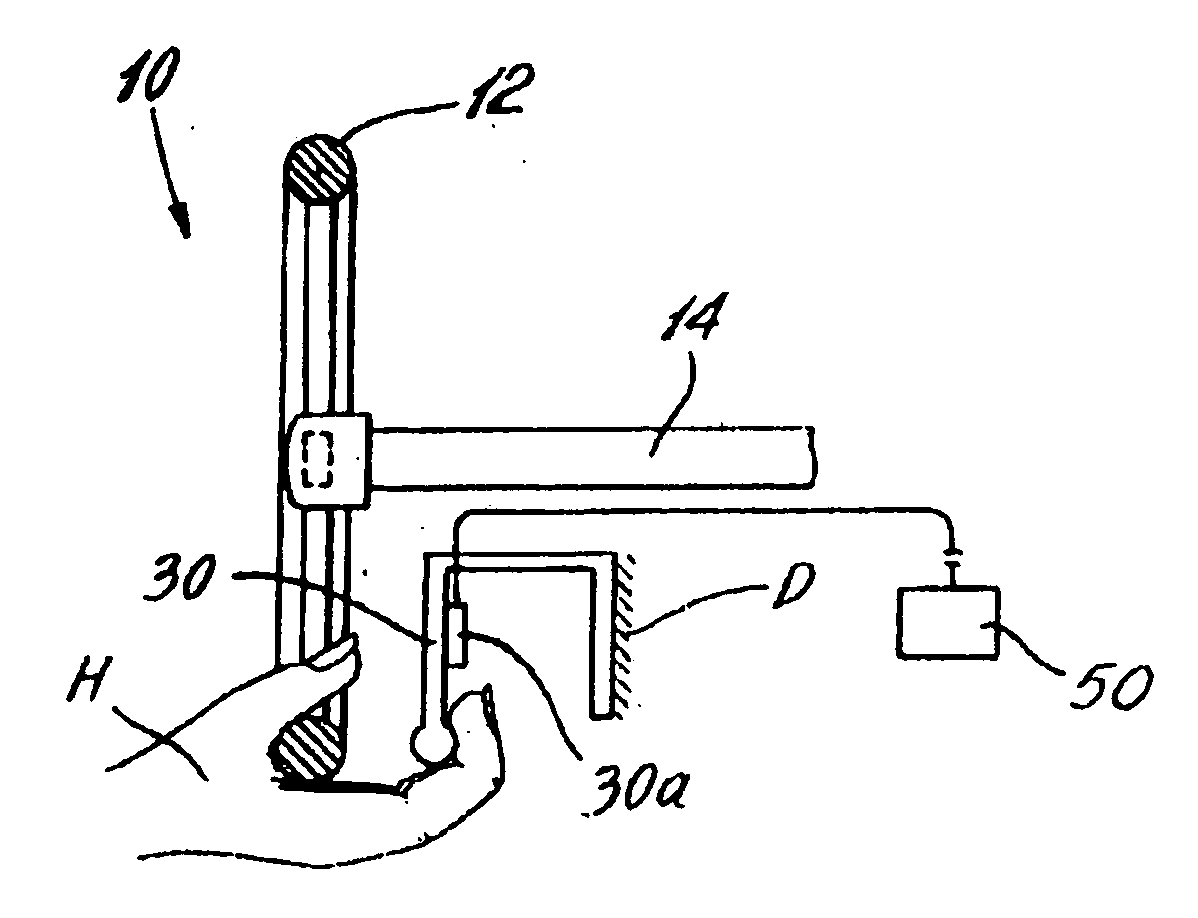
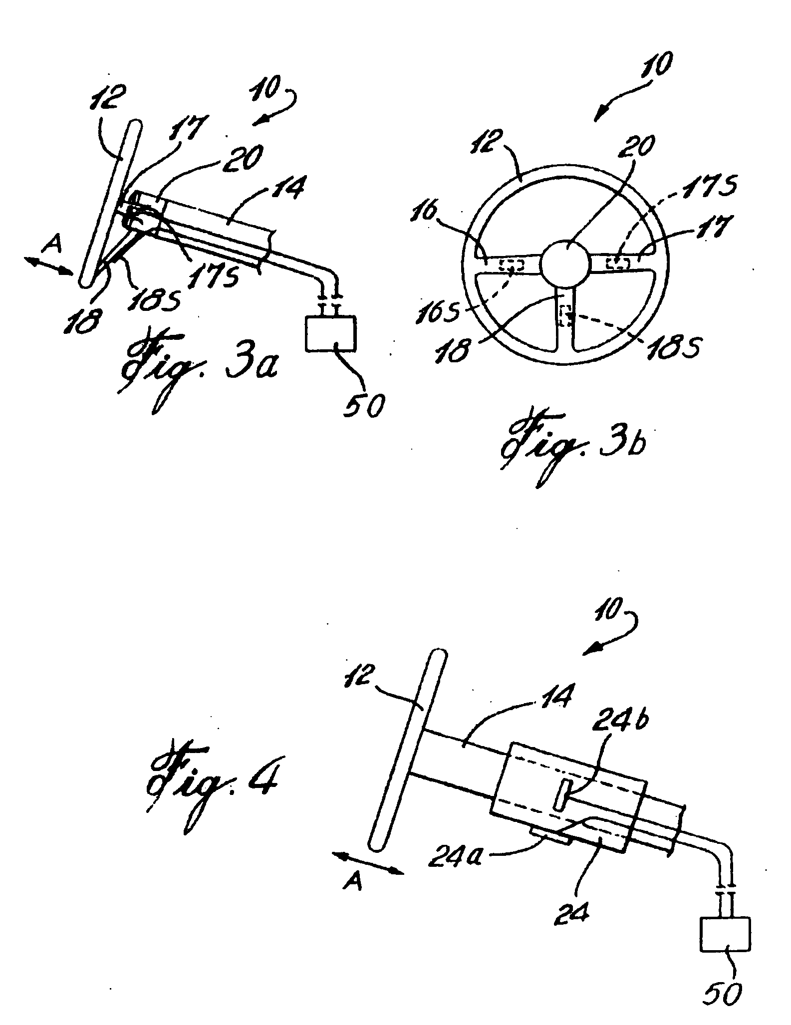
[0028] Referring now to the drawings and, more particularly, to FIGS. 3a and 3b, a steering wheel is generally shown at 10. The steering wheel 10 is comprised of a rim 12 mounted to a steering column 14 by horizontal spokes 16 and 17 and a vertical spoke 18 converging at a hub portion 20. Strain gauge sensors 16S, 17S and 18S are secured to the horizontal spokes 16, 17 and the vertical spoke 18, respectively. When the driver exerts a push or a pull on the steering wheel 10 as shown by arrow A, the horizontal spokes 16 and 17 and the vertical spoke 18 are subject to deformation, which is picked up by the strain gauge sensors 16S, 17S and 18S. A signal is then sent to a processing unit 50 to which the strain gauge sensors 16S, 17S and 18S are wired. The processing unit 50 will immediately power-assist the brakes in outputting brake torque proportionally to the driver's input, whether it be through the master cylinder or directly to the brakes.

[0029] The advantage of the above describ...


PUM


Abstract

An apparatus for controlling the braking of a vehicle having a brake system. The apparatus comprises a brake actuating member (10) mounted to the vehicle within hand reach of a driver. Strain gages (17S, 18S) are adapted for being disposed in communication with the brake actuating member (10). A processing unit is connected to the strain gages (17S, 18S) for receiving input therefrom and for proportionally power-assisting the brake system of the vehicle, whereby the driver, by exerting varying pressure (A) by hand on the brake actuating member (10), controls the braking of the vehicle.

Description

CROSS-REFERENCE TO RELATED APPLICATIONS [0001] This application is a Continuation of co-pending application Ser. No. 10 / 220,848 filed on Nov. 6, 2002, and for which priority is claimed under 35 U.S.C. § 120, which claims priority under 35 U.S.C. § 120 to International Application No. PCT / CA01 / 00279 filed Mar. 5, 2001, the entire contents of all are hereby incorporated by reference.BACKGROUND OF THE INVENTION [0002] 1. Field of the Invention [0003] The present invention relates to brake systems and, more particularly, to the adaptation of sensors thereto for accelerating the actuating thereof. [0004] 2. Description of the Prior Art [0005] In the world of automotive industry, the brakes are controlled by means of a brake pedal which mechanically actuates a hydraulic or pneumatic master cylinder. This master cylinder converts the mechanical effort of a driver in hydraulic or pneumatic pressure, which will actuate receiving pistons disposed in the brake of each wheel. [0006] The disadva...

Claims


Application Information

Patent Timeline
Patent Type & Authority Applications(United States)
IPC IPC(8): B62B5/04B60T7/08B60T7/10B60W30/18
CPCB60K2741/003B60T7/10B60T7/107B60W30/18B60W2540/10B60W2540/12
Inventor CONSTANS, ALAIN
Owner CONSTANS ALAIN
Why Eureka
Try Eureka