Method and system for sampling at least one antenna

a technology for antennas and antennas, applied in the field of methods and systems for sampling at least one antenna, can solve the problems of high production cost, unsuitable diagnosis system, and difficult to detect the functional test of the antenna in the installed state, and achieve the effects of low cost, low cost and simple arrangemen

Inactive Publication Date: 2006-04-20
DAIMLER AG
View PDF3 Cites 34 Cited by
  • Summary
  • Abstract
  • Description
  • Claims
  • Application Information

AI Technical Summary

Benefits of technology

[0004] The invention is thus based on a method for testing at least one antenna in a vehicle, in which diagnosis can be carried out at all the frequencies in one band, for example a radio, TV, mobile radio or ISM band, at low costs and in a particularly simple manner. Furthermore, the invention provides a particularly simple arrangement for testing the antenna in the installed state. In the invention knowing the level of the test signal source is not necessary, thus making it possible to use a low-cost test signal source.
[0005] The advantages which are achieved by the invention are, in particular, that a noise signal from an uncalibrated noise source is injected into the antenna as a test signal by means of a controllable coupling module. If there is only a single antenna, the noise signal which is being reflected at the antenna input is evaluated as the received signal in a test module. For this purpose, the received signal is advantageously used to determine an instantaneous transmission coefficient, which represents the relevant antenna, at a predetermined frequency or at two or more frequencies in a band. The instantaneous transmission coefficient is compared with a reference transmission coefficient, which represents the transmission behavior of the noise source via the coupling module to the antenna and back to the receiver. A serviceable antenna produces minimal reflection at the antenna.
[0006] In the case of a multiple antenna system comprising two or more antennas, the noise signal transmitted between the antennas is analyzed and assessed alternatively or in addition to the noise signal which has been reflected at the respective antenna inputs. For this purpose, the noise signal is injected into the antenna or antennas from the uncalibrated noise source or test signal source by means of a coupling circuit, is received by an adjacent antenna, and is analyzed by means of a transmission matrix in the test module, in particular in the receiver, for example an audio or video tuner. Such functional monitoring or diagnosis using a simple uncalibrated noise source, which in the simplest case is formed by a source in the receiver itself, allows a particularly low-cost and simple arrangement. In particular, the production cost is particularly low. As a result of the use of already existing components in the receiver, the arrangement generally requires little space and, as a result of this and due to the integration of the test module, for example, in a vehicle, there is no need for complex test transmitters at the end of the production line or for servicing when the diagnosis or test method is used in the vehicle field.
[0007] Furthermore, the use of a noise signal as the test signal allows a diagnosis covering all the frequency bands to be carried out on the antenna or antennas. In particular, a test such as this based on a noise signal also allows evaluation relating to external influences on the serviceability of the antenna or antennas, such as snow or other external interference signals, which lead to incorrect diagnosis in the case of the conventional systems based on the prior art. In particular, this ensures that the antenna or antennas is or are tested and monitored in the installed state as well, and thus, for example, while a vehicle is being driven.

Problems solved by technology

A functional test with the antenna in the installed state has been particularly complex and required a particularly large amount of effort.
One disadvantage of this circuit arrangement is that it has a calibrated signal generator to produce a test signal, which signal generator transmits a discrete test signal exclusively at the frequency to which the receiver is tuned.
Furthermore, the circuit arrangement is not suitable for diagnosis which accounts for external influences, such as snow or ice.
However, this system is highly costly to produce, as a result of the use of the pseudo-random noise signal source, which produces a high-speed digital signal, as well as the correlation receiver.
In particular, the production cost is particularly low.
In particular, a test such as this based on a noise signal also allows evaluation relating to external influences on the serviceability of the antenna or antennas, such as snow or other external interference signals, which lead to incorrect diagnosis in the case of the conventional systems based on the prior art.

Method used


Image

  • Method and system for sampling at least one antenna
  • Method and system for sampling at least one antenna
  • Method and system for sampling at least one antenna

Examples


Embodiment Construction

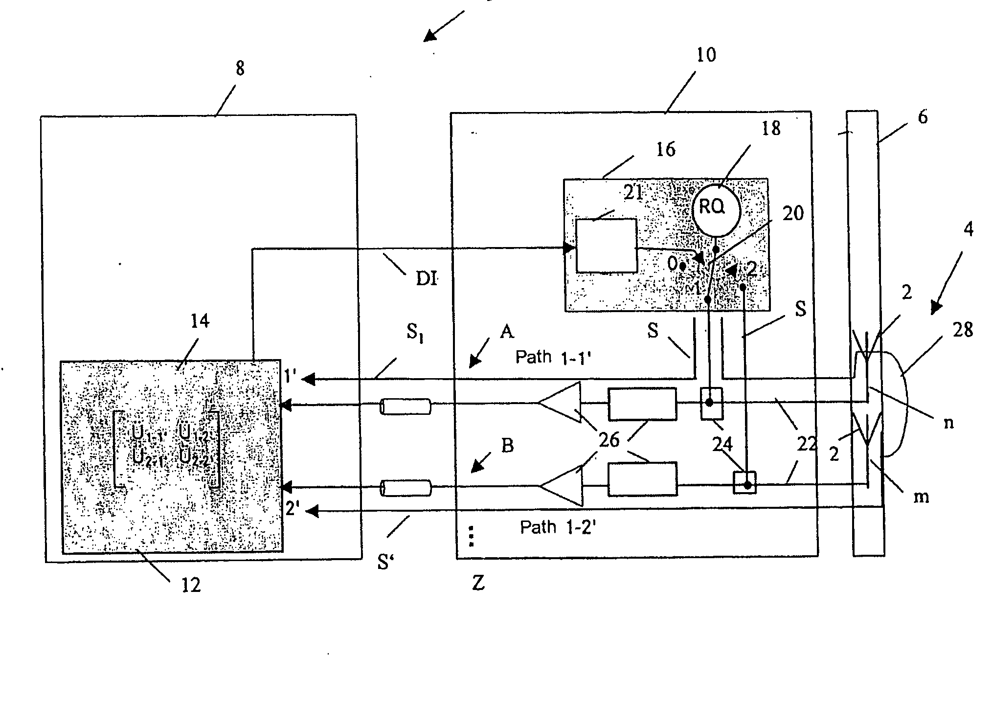
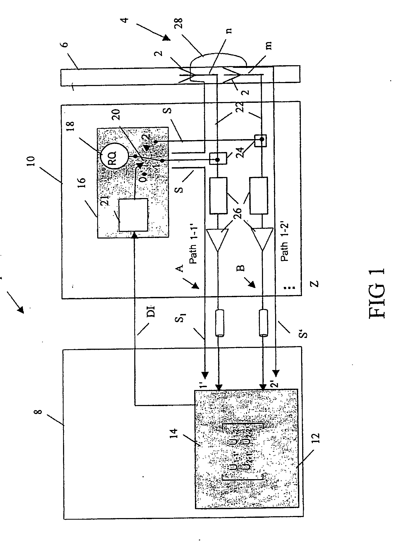
[0015]FIG. 1 shows a circuit arrangement 1 for testing an antenna system 4, which comprises two or more antennas 2, on a vehicle. The antenna system 4 is integrated in a glass pane 6, for example the rear windshield, a side window, or the rear window and / or side window or windows of the vehicle. The circuit arrangement 1 has a receiver module 8 and a coupling module 10, which is arranged between the antennas 2 and the receiver module 8. The antenna or coupling module 10 is used for injection of a noise signal S into the respective antenna 2 and into the receiver module 8, which is also referred to as a tuner. The receiver module 8 also has a test module 12 for determination of an instantaneous transmission coefficient (Üvi) on the basis of the ratio between the noise signal component S′ that is injected via the antennas, and the noise signal component S1 which is transmitted directly from the noise source to the receiver. In order to determine the serviceability of the respective an...


PUM


Abstract

A method for testing at least one antenna having a receiver module and a coupling module which is arranged between the antenna and the receiver module. The antenna and the receiver module are supplied with a noise signal as a test signal by the coupling module. An instantaneous transmission coefficient, which indicates the ratio between a first noise signal (which is passed to the test module via a first path without passing through the at least one antenna) and a second noise signal (which is passed to the test module from the noise source via a second path which passes via the at least one antenna) being determined, and being compared with a reference transmission coefficient, which is stored in a transmission matrix, by a test module. An arrangement for carrying out the method is also provided.

Description

BACKGROUND AND SUMMARY OF THE INVENTION [0001] The invention relates to a method and an arrangement for testing at least one antenna, in particular a multiple antenna system in a vehicle. [0002] As the number of antennas on vehicles increases, it is becoming necessary to carry out a functional test of the antenna system. Functional tests such as these are normally carried out in the removed state. A functional test with the antenna in the installed state has been particularly complex and required a particularly large amount of effort. For example, DE 196 18 333 A1 describes a circuit arrangement for functional testing of mobile broadcast radio receiving systems in the installed state. One disadvantage of this circuit arrangement is that it has a calibrated signal generator to produce a test signal, which signal generator transmits a discrete test signal exclusively at the frequency to which the receiver is tuned. Furthermore, the circuit arrangement is not suitable for diagnosis whi...

Claims


Application Information

Patent Timeline
Patent Type & Authority Applications(United States)
IPC IPC(8): G01S7/40G01R29/08H04B1/18H04B7/08H04B17/00
CPCH04B17/20H04B7/0822
Inventor DEININGER, JUERGENGOTTSCHALK, BERNDLINDENMEIER, STEFANREICHERT, GUENTER
Owner DAIMLER AG
Why Eureka
Try Eureka