
Disk device, method for controlling disk devic, and program for disk device controlling method

a technology for controlling disk devices and disk drives, applied in the field of disk drives, can solve the problems of reducing the efficiency of disk drive power dissipation, and achieve the effect of reducing the power dissipation of disk drives and improving efficiency

Inactive Publication Date: 2006-04-20
SONY CORP
View PDF0 Cites 7 Cited by
  • Summary
  • Abstract
  • Description
  • Claims
  • Application Information

AI Technical Summary

Benefits of technology

[0005] The present invention has been made in view of the above circumstances and provides a disk drive, a disk drive controlling method, and a disk drive controlling method program for reducing the dissipation of power more efficiently than before.
[0007] The disk drive of the invention, as outlined above, records and / or reproduces the continuous data stream intermittently to and / or from the disk-type recording medium in increments of the predetermined amount of data. Parts of the driving circuits for driving the disk-type recording medium are turned off temporarily while the data stream is not being written to the disk-type recording medium in each idle time during the intermittent recording and / or reproduction of the data stream. The driving circuit parts to be deactivated are switched depending on the length of the idle time. Illustratively, the recording or reproduction of streaming data at a low data transfer rate may entail a relatively long idle time during the operation. In that case, many of the circuits in use may be deactivated in each idle time during the recording or reproduction, whereby power is saved significantly. On the other hand, if the idle time is relatively short, the circuits to be turned off in each idle time during the operation are limited so as not to affect the repeated steps of the recording or reproduction. In this manner, power supply is controlled more scrupulously so that power dissipation is reduced more efficiently than before.
[0009] Where the disk drive controlling method above according to the invention is used in conjunction with the disk drive, power dissipation of the disk drive is also reduced more efficiently than before.
[0011] Where the disk drive controlling method program above according to the invention is used in conjunction with the computer for controlling the disk drive, power dissipation of the disk drive is also reduced more efficiently than before.

Problems solved by technology

Illustratively, the recording or reproduction of streaming data at a low data transfer rate may entail a relatively long idle time during the operation.

Method used


Image

  • Disk device, method for controlling disk devic, and program for disk device controlling method
  • Disk device, method for controlling disk devic, and program for disk device controlling method
  • Disk device, method for controlling disk devic, and program for disk device controlling method

Examples


Embodiment Construction

[0024] One preferred embodiment of this invention will now be described in detail with reference to the accompanying drawings.

(1) Structure of the Preferred Embodiment

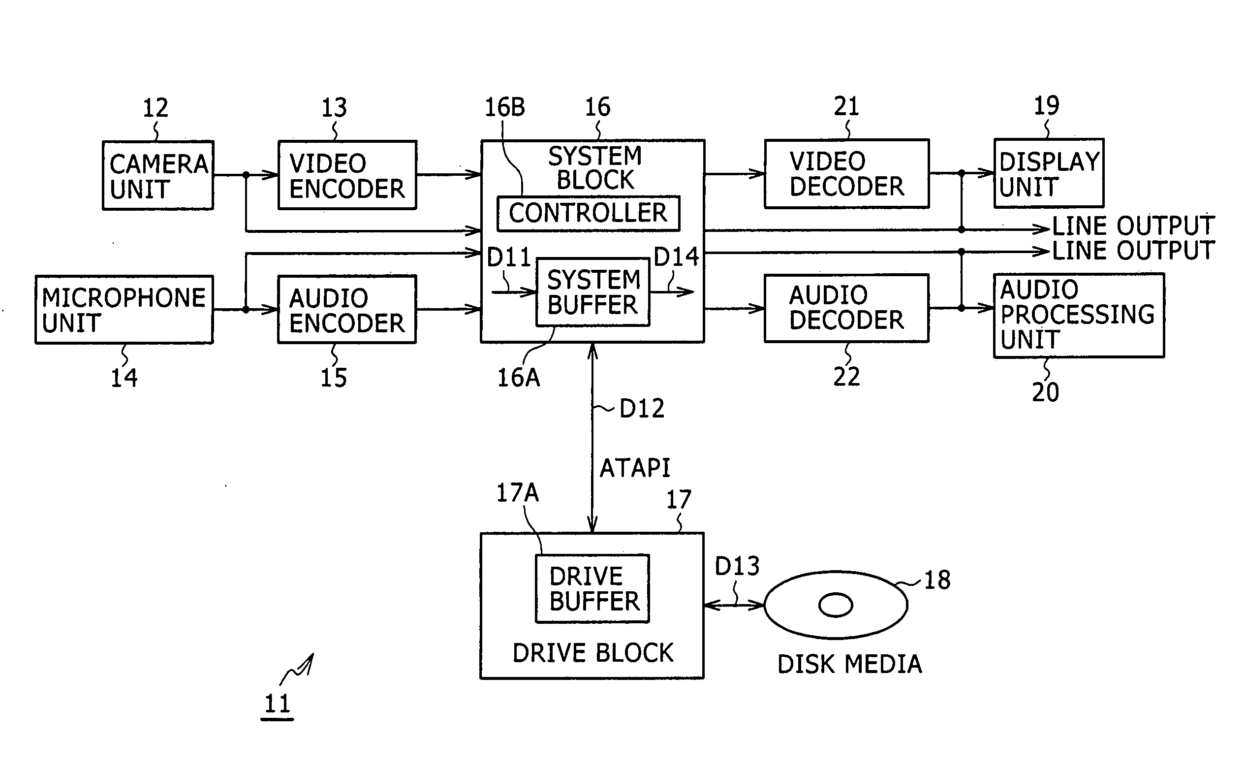
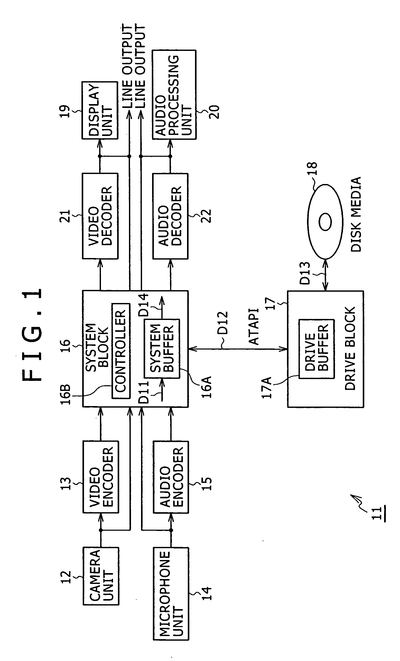
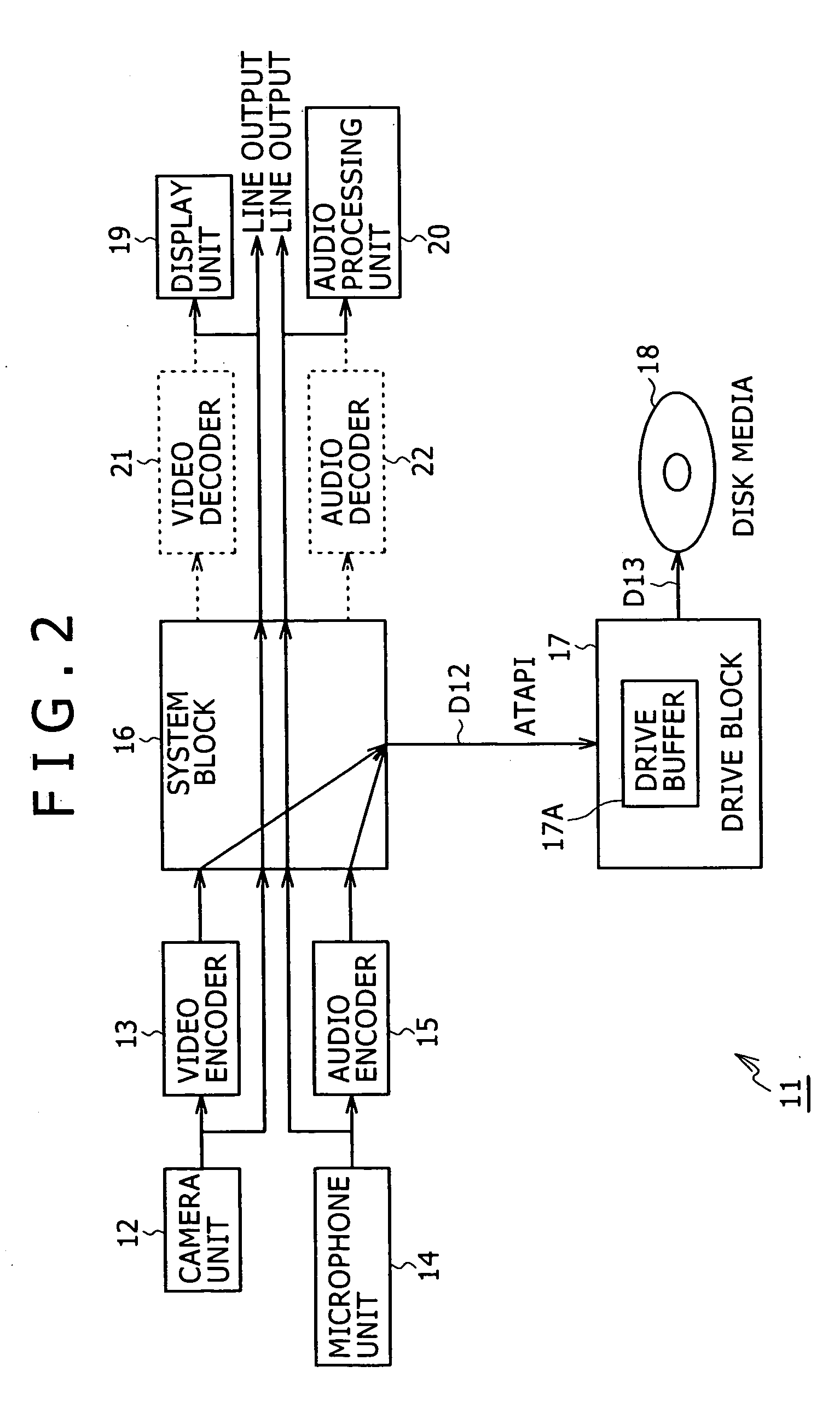
[0025]FIG. 1 is a block diagram showing a recording apparatus embodying this invention. The recording apparatus is a portable camcorder that adopts the recording / reproducing system of an optical disk drive replacing the magnetic tape-based recording / reproducing system of conventional camcorders.

[0026] In the recording apparatus 11, a camera unit 12 takes pictures of a desired subject through a lens arrangement and outputs video data representative of the pictures taken. A video encoder 13 receiving the video data from the camera unit 12 compresses the received data illustratively in MPEG format for output. More specifically, the video encoder 13 compresses the video data at a so-called constant bit rate that keeps the amount of generated data constant and switches the amount of generated data under control of a sys...


PUM


Abstract

This invention relates illustratively to a portable video recorder that uses an optical disk. The inventive recorder is arranged to switch the degree of power conservation depending on the length of an idle time T2 during intermittent recording and / or reproduction of continuous data to and / or from the optical disk.

Description

TECHNICAL FIELD [0001] The present invention relates generally to a disk drive, a disk drive controlling method, and a disk drive controlling method program. More particularly, the invention relates to a portable video recorder that uses an optical disk and by extension to techniques for switching the degree of power conservation in keeping with the length of an idle time during the intermittent recording or reproduction of continuous data, whereby power dissipation is reduced more efficiently than before. BACKGROUND ART [0002] Conventional camcorders were designed to record video data representing pictures taken of desired subjects onto a recording medium in the form of a magnetic tape. Camcorders of this type were arranged to switch their overall operation into standby mode if they were inactive for an extended period of time. The mode switching feature was intended to reduce the dissipation of the battery-based power supply. [0003] In recent years, various recording apparatuses u...

Claims


Application Information

Patent Timeline
IPC IPC(8): G11B5/09G11B19/00G11B20/10H04N5/85
CPCG11B19/00H04N5/85G11B20/10G11B19/02
Inventor MATSUNO, KATSUMIARIDOME, KENICHIROMAEDA, YASUAKI
Owner SONY CORP
Learn More