
Apparatus and method of analyzing packetized data spanning over multiple clock cycles

Inactive Publication Date: 2006-04-20
TEKTRONIX INC
View PDF14 Cites 44 Cited by
  • Summary
  • Abstract
  • Description
  • Claims
  • Application Information

AI Technical Summary

Benefits of technology

[0012] The subject invention enables the tracking of packet style data as well as the release of resources to enable thereby more complex triggering conditions to be specified for a trigger machine, illustratively of a logic analyzer. In particular, the in

Problems solved by technology

However, since all of the information in a packet is not available within a single clock cycle, it takes most, if not all, of the word recognizers, and most of the trigger states, to define just a simple trigger event.
Since the trigger machine has used most, if not all of its resources (word recognizers, trigger states, and the like) just to track an incoming packet, the trigger machine cannot perform other (additional) tasks such as, for example, “wait for packet A to occur and then trigger when packet B occurs”.
While useful, this solution is relatively inflexible because it only allows a user to compare the first 24 bytes.
For example, if the header of the packet is large (e.g., about 24 bytes), this solution may not be able to perform desired compare matches in the data payload or tail of the packet, or portions thereof.

Method used


Image

  • Apparatus and method of analyzing packetized data spanning over multiple clock cycles
  • Apparatus and method of analyzing packetized data spanning over multiple clock cycles
  • Apparatus and method of analyzing packetized data spanning over multiple clock cycles

Examples


first embodiment

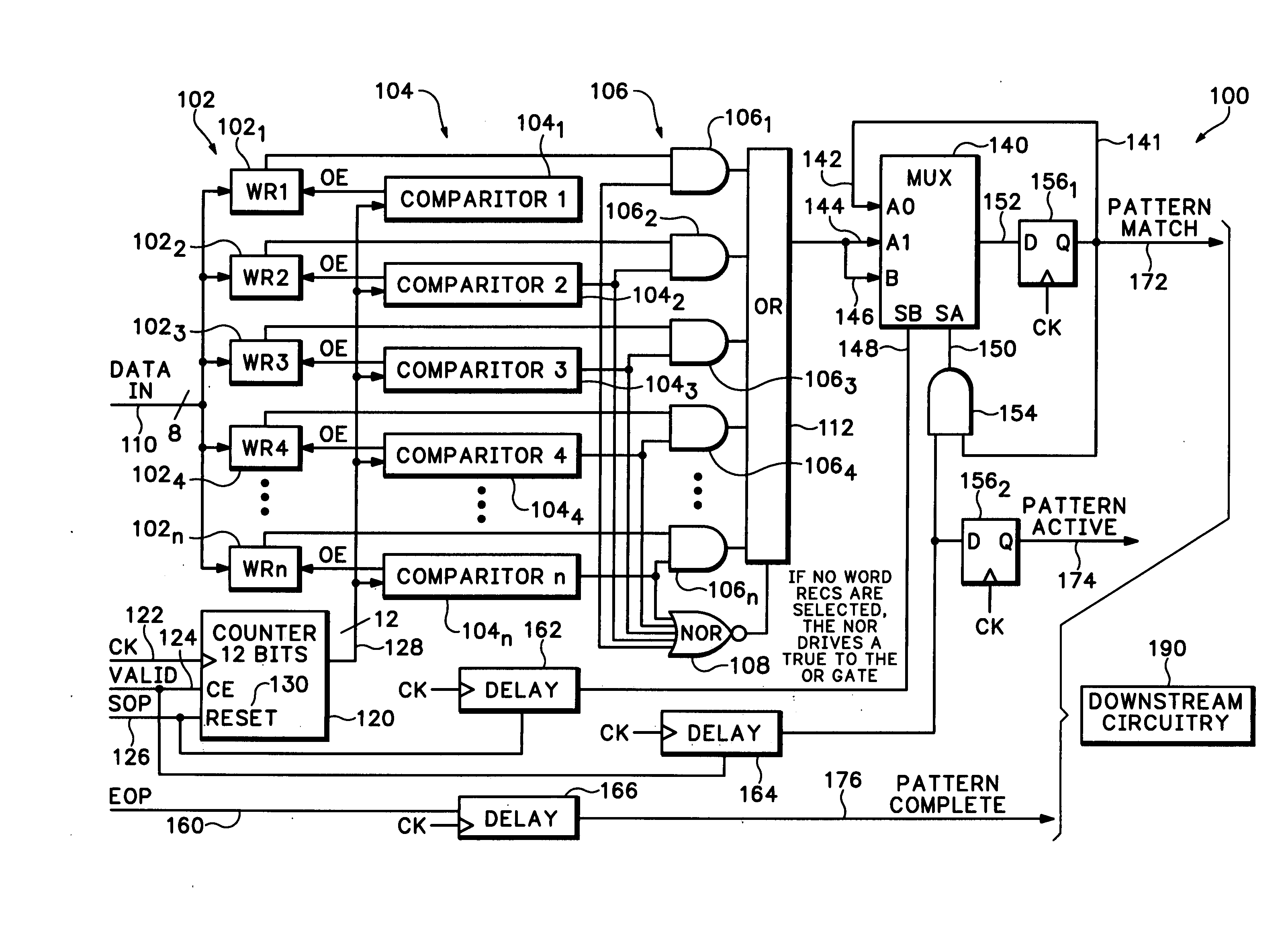
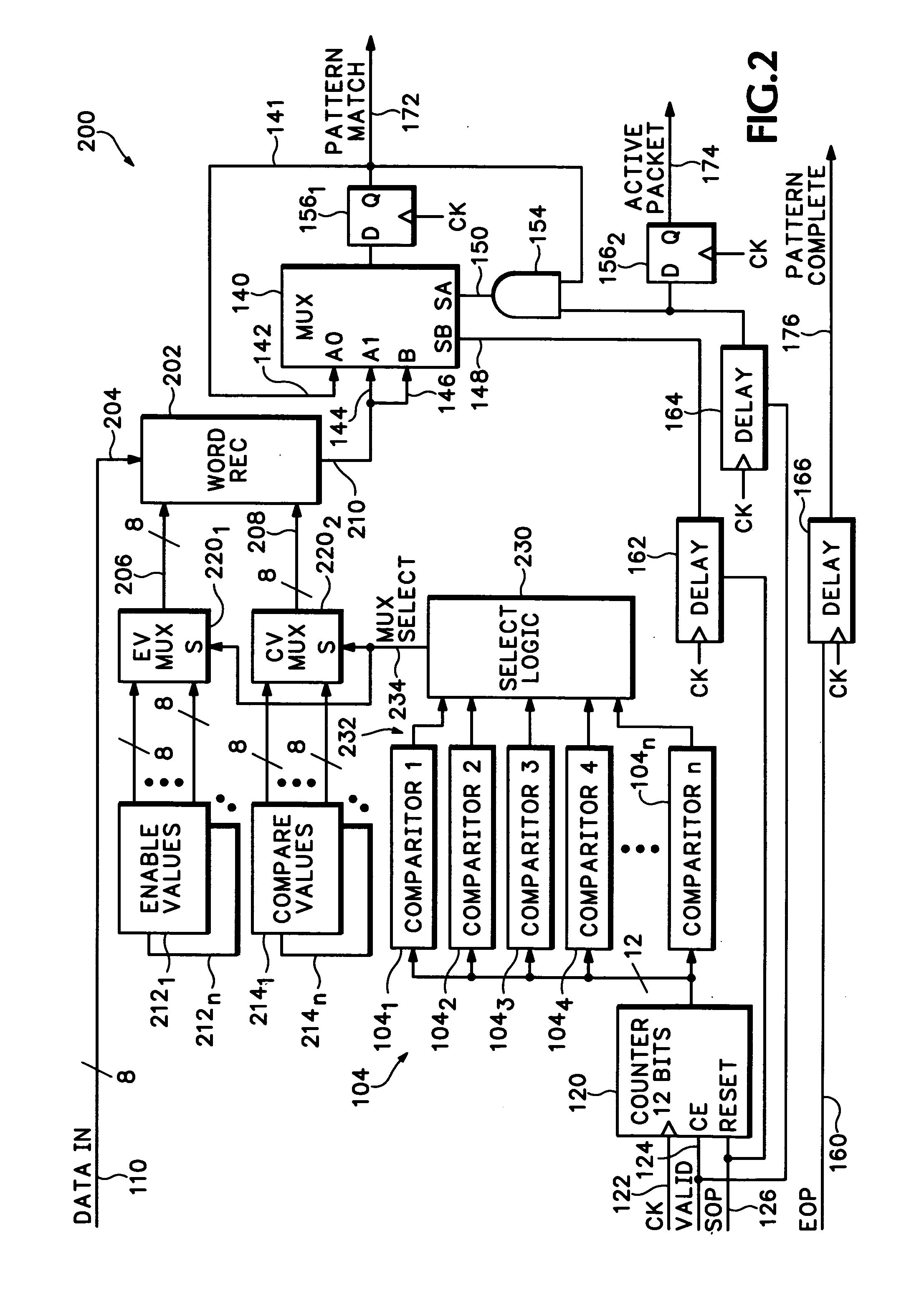
[0049]FIG. 2 is a schematic diagram of a Pattern Match circuit 200 according to an alternate embodiment of the present invention. The Pattern Match circuit 200 of FIG. 2 differs from FIG. 1 in that instead of having multiple word recognizers 1021 through 102n (i.e., one word recognizer for each respective counter comparator 106), a single word recognizer 202 is utilized. In this embodiment, counter comparators 106 select a different compare and enable value for the single word recognizer 202, depending on the count value. Each of these counter comparators is capable of enabling the one word recognizer at the appropriate packet data offset count.

[0050] Specifically, the Pattern Match circuit 200 of FIG. 2 comprises a counter 120, a plurality of comparators 104, select logic 230, a plurality of enable value registers 2121 through 212n (collectively enable value registers 212), a plurality of compare value registers 2141 through 214n (collectively compare value registers 214), an enabl...

embodiment 200

[0052] It is noted that in the block diagram for the first Pattern Match circuit 100 of FIG. 1, the compare and enable registers for the word recognizers are not shown. The function they represent is assumed to be part of each word recognizer 1021 through 102n. By comparison, in this second circuit embodiment 200, the enable and compare values are respectively shown as registers 212 and 214 that are external to the single word recognizer 202. Further, an enable and compare register pair (212 and 214) are associated with each comparator 104 in the circuit. Accordingly, since there are n comparators 104 (where n is an integer greater than 1), the circuit 200 includes n enable value registers 212n and n compare registers 214n. As such, enable and compare value register pairs 2121 and 2141 are associated with comparator 1041, enable and compare value register pairs 2122 and 2142 are associated with comparator 1042, and so forth.

[0053] Each enable value register 212n has an output that i...


PUM


Abstract

A method and apparatus for processing packetized data spanning multiple clock cycles includes at least one comparator, for comparing a present clock cycle count to a reference clock cycle count, wherein the reference clock cycle values may be anywhere within the packet and may be non-contiguous with other reference clock cycle values. At least one word recognizer, compares a presently clocked word to a reference word, and an output circuit provides an indication of a favorable word comparison that occurred in response to a favorable clock cycle count comparison.

Description

BACKGROUND OF THE INVENTION [0001] 1. Field of the Invention [0002] The present invention generally relates to analyzing packetized information and, more specifically, to analyzing packetized information spanning many clock cycles. [0003] 2. Description of the Related Art [0004] Logic Analyzers are test and measurement instruments used, for example, to monitor bus traffic to facilitate development and testing of microprocessor systems. Logic analyzers allow inspection of patterns (i.e., particular arrangements of logic states) in logic signals, and may be configured to detect the occurrence of selected events. [0005] Many modern communication buses (e.g., 3GIO, Hypertransport and the like) use a packet-based protocol in which each byte or word of a packet is conveyed over the bus in response to the occurrence of a clock signal. A packet may include only a few bytes, or may include thousands of bytes of data that may span many clock cycles. [0006] Capturing desired data frequently hi...

Claims


Application Information

Patent Timeline
IPC IPC(8): H04J3/06
CPCG01R31/3177H04L7/042
Inventor HOLADAY, DAVID A.CHEREN, GEOFFREY D.
Owner TEKTRONIX INC
Learn More