Moving image encoding apparatus and control method therefor

a technology of moving image and encoding apparatus, which is applied in the direction of color television with bandwidth reduction, television system, instruments, etc., can solve the problem of dramatic increase in the volume of calculations to be performed

Inactive Publication Date: 2006-04-20
CANON KK
View PDF5 Cites 20 Cited by
  • Summary
  • Abstract
  • Description
  • Claims
  • Application Information

AI Technical Summary

Benefits of technology

[0017] The present invention is conceived in light of problem s in the conventional technology like those described above, and has as its object to make it possible to select an effective reference image as the reference image to be used in moving image encoding using motion prediction.

Problems solved by technology

In addition, with an encoding method like the H.264 method, which stores a plurality of image in the frame memory and can use all of them as reference images, there is the problem that the volume of calculations that must be performed increases dramatically when searching for the motion vector from among all the images in the frame memory.

Method used


Image

  • Moving image encoding apparatus and control method therefor
  • Moving image encoding apparatus and control method therefor
  • Moving image encoding apparatus and control method therefor

Examples


first embodiment

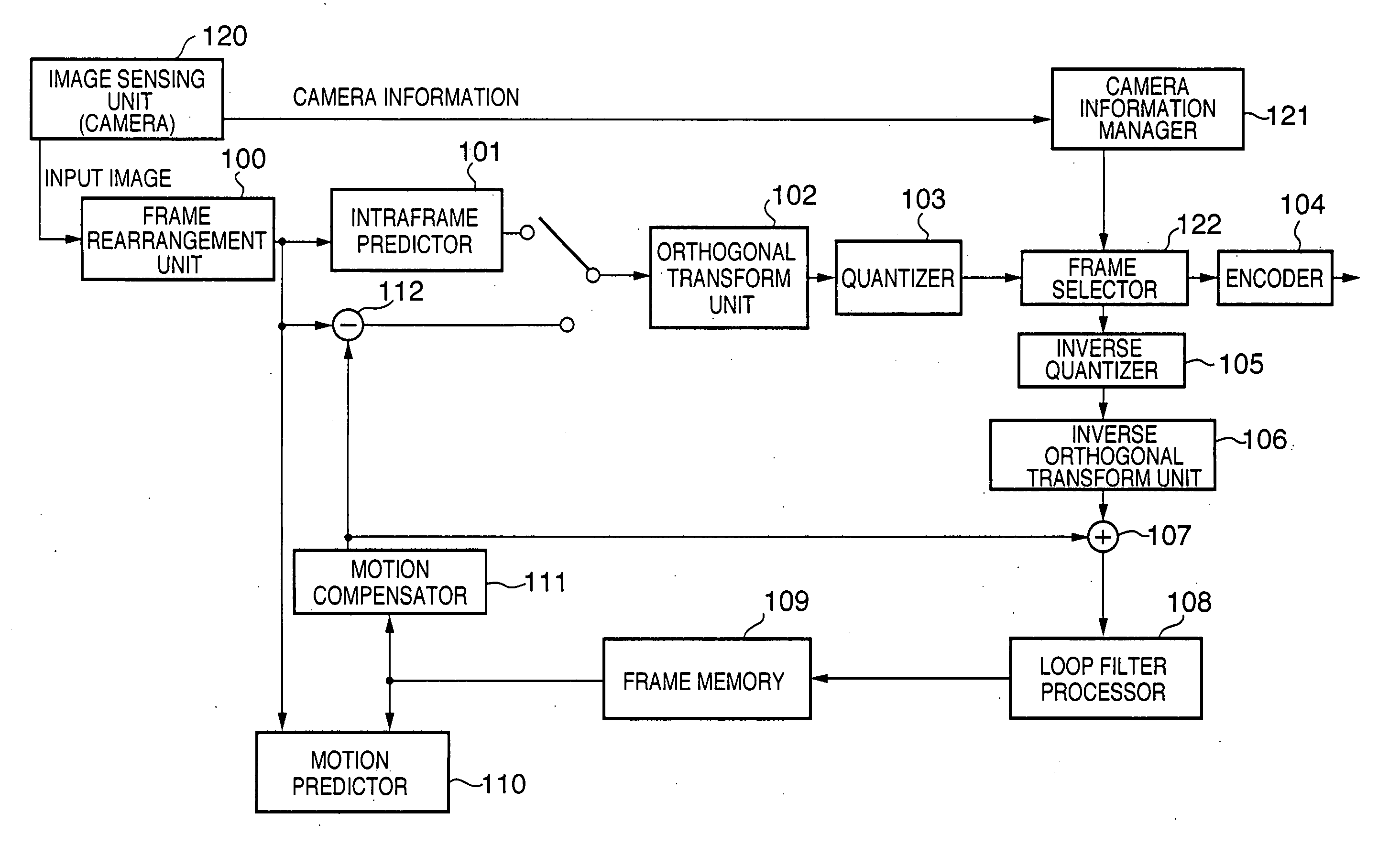
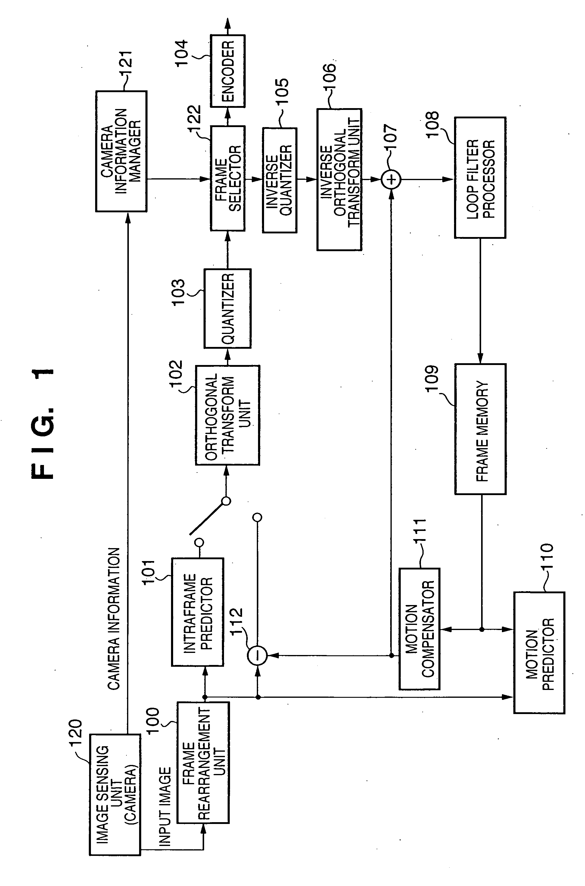
[0042]FIG. 1 is a block diagram showing an example of the configuration of a digital video camera as a moving image encoding apparatus according to a first embodiment of the present invention. The digital video camera of the present embodiment is characterized by selecting a locally-decoded image recorded in the frame memory as the reference image using the camera information.

[0043] In FIG. 1, the digital video camera of the present embodiment is comprised of a frame rearrangement unit 100, an intraframe predictor 101, an orthogonal transform unit 102, a quantizer 103, an encoder 104, an inverse quantizer 105, an inverse orthogonal transform unit 106 and an incrementer 107, and further comprises a loop filter processor 108, a frame memory 109, a motion predictor 110, a motion compensator 111 and a decrementer 112, that is, the components of the same name in FIG. 13 generalized as the fundamental configuration. In addition to the foregoing elements, the digital video camera of the p...

second embodiment

[0086] In the first embodiment of the present invention, image frames not to be recorded in the frame memory are identified on the basis of the camera information, with frames likely to be of high continuity stored in the frame memory 109 as reference image candidate images.

[0087] A second embodiment is characterized by using the camera information to select images that should not be kept in the frame memory and which should be deleted first. In this embodiment as well, as with the first embodiment, the description proceeds using the example of a moving image compression-encoding apparatus equipped with an image sensing capability.

[0088]FIG. 6 is a block diagram showing an example of the configuration of a video camera as the moving image compression-encoding apparatus of the present embodiment, with the same elements as the first embodiment given the same reference numerals.

[0089] In FIG. 6, because the distinctive feature of the present embodiment is the use of a camera informa...

third embodiment

[0107] A third embodiment is characterized by determining which of the image frames recorded in the frame memory are to be detected based on the camera information. In this embodiment as well, as with the embodiments described above, the description proceeds using the example of a moving image compression-encoding apparatus equipped with an image sensing capability.

[0108]FIG. 8 is a block diagram showing an example of the configuration of a video camera as the moving image compression-encoding apparatus of the present embodiment, with the same elements as the first embodiment given identical reference numerals.

[0109] As shown in FIG. 8, because the distinctive feature of this embodiment is the operation of the camera information manager 821 and the motion predictor 810, a description is given only of these elements. It should be noted that, in the present embodiment, the frame memory 109 is capable of recording five frames of images.

[0110] As with the embodiments described above,...


PUM


Abstract

Detects from camera information frames of probable low continuity, such as frames in which a strobe is flashed, and does not use such frames as candidate images for a reference image. As a result, the possibility that the candidate images in the frame memory are images of high continuity with a frame to be encoded increases, enabling efficient motion vector detection and making possible low data-generation-volume encoding.

Description

FIELD OF THE INVENTION [0001] The present invention relates to a moving image encoding apparatus that compression-encodes a moving image and a control method therefor, and more particularly, to a moving image encoding apparatus that predicts interframe motion and a control method therefor. BACKGROUND OF THE INVENTION [0002] In recent years, in order to store and transmit moving image information as digital data, a technology that encodes image information at a high compression ratio and with high picture quality is sought. As a compression technique for image information, a compression-encoding method in which an orthogonal transform such as a discrete cosine transform and motion prediction / motion compensation are combined has come to be widely diffused, as typified by the MPEG method. [0003] In addition, in recent years, as an encoding method that aims for an even higher compression ratio and even better picture quality, there is ITU-T H.264 / AVC(MPEG4 AVC). It is known that, compar...

Claims


Application Information

Patent Timeline
Patent Type & Authority Applications(United States)
IPC IPC(8): H04N11/04H04N11/02H04N7/12H04B1/66H04N19/50H04N19/102H04N19/105H04N19/134H04N19/142H04N19/152H04N19/172H04N19/189H04N19/196H04N19/423H04N19/503H04N19/577H04N19/58H04N19/61H04N19/625H04N19/91
CPCH04N19/197H04N19/172H04N19/46H04N19/196H04N19/573H04N19/61H04N19/136H04N19/142H04N19/87H04N19/102
Inventor KITAJIMA, KOTARO
Owner CANON KK
Why Eureka
Try Eureka