
Unified messaging architecture

a messaging architecture and messaging technology, applied in the field of messaging systems, to achieve the effect of facilitating the acceptance or cancellation of calendar items

Inactive Publication Date: 2006-04-20
MICROSOFT TECH LICENSING LLC
View PDF13 Cites 95 Cited by
  • Summary
  • Abstract
  • Description
  • Claims
  • Application Information

AI Technical Summary

Benefits of technology

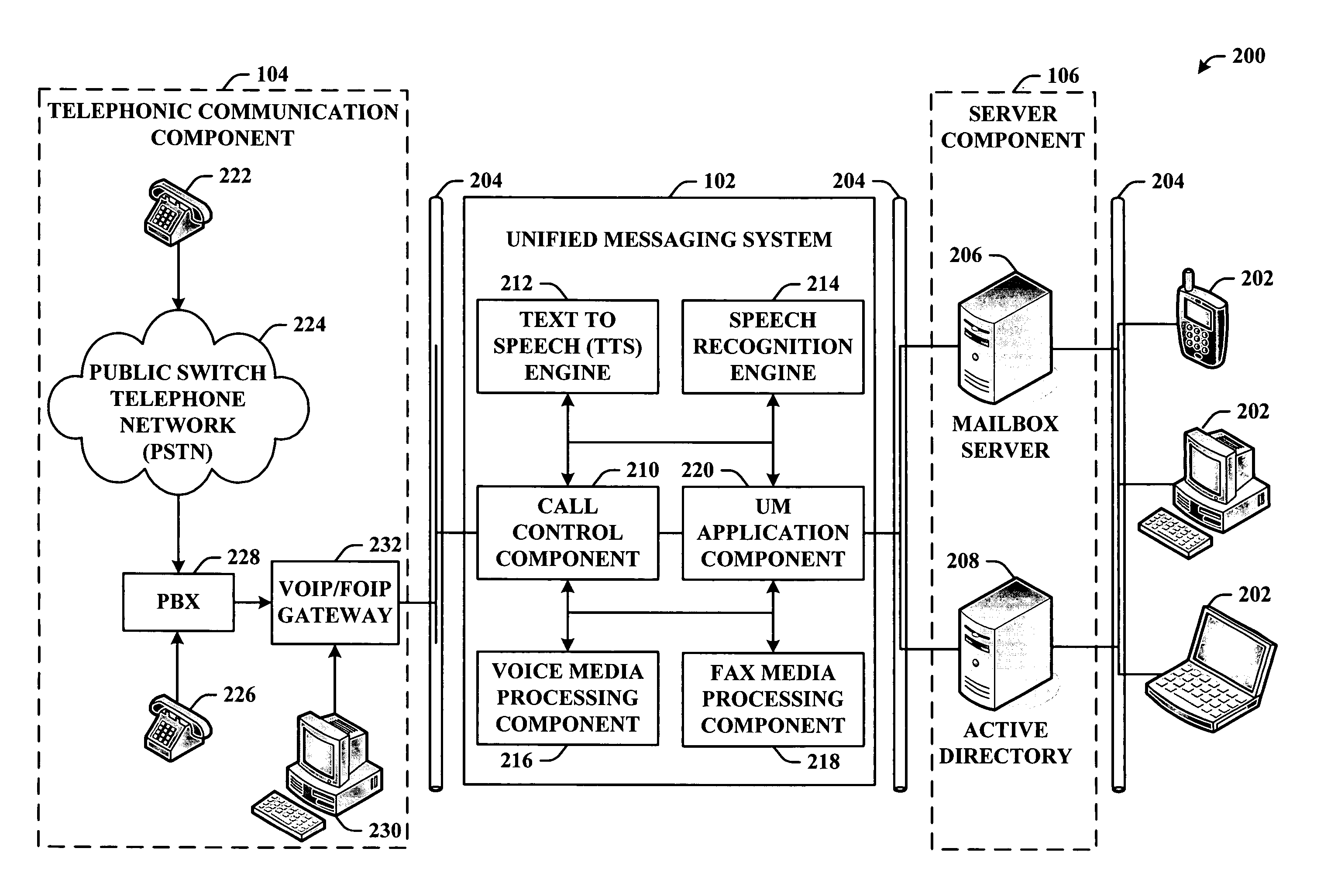
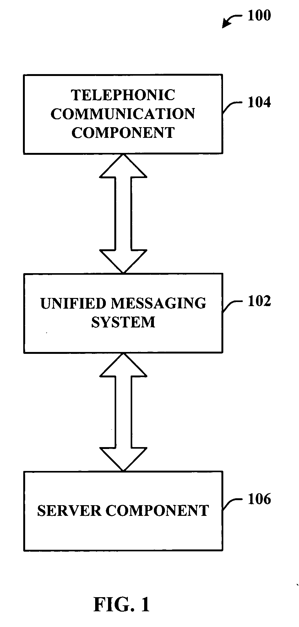
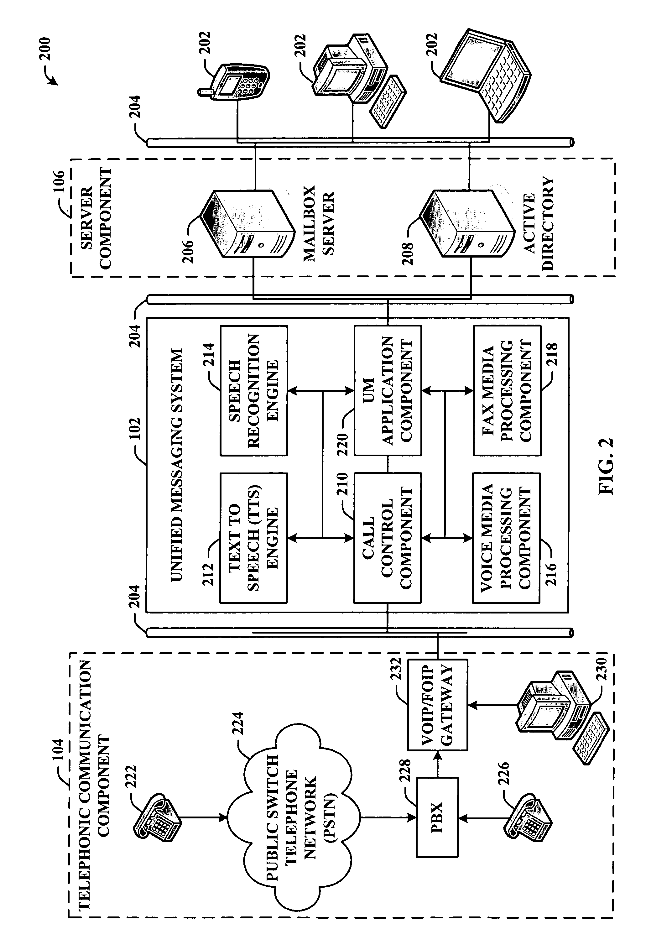
[0009] The subject invention, in one aspect thereof, allows a user to connect to a server (e.g., messaging server) via a telephonic communications component thereby accessing the rich information therein. The invention comprises a system and / or methodology that unifies a telephonic communications component and / or system with a messaging server component and / or system. For example, with access to an application programming interface, the invention can add functionality to enable telephonic generation and retrieval of email communications. The invention can further facilitate accepting or canceling calendar items (e.g., meeting requests and appointments) via a telephonic communications device.
[0010] With reference to another aspect, since both the telephone client and the email client can employ the same backend information, the system can effect synchronization of an “Out of the Office” (OOF) greeting status for both systems. By way of example, today, users frequently set an OOF status on both an email system and telephone voicemail system. Because the content of an extended absence email auto-reply and a voicemail extended absence OOF greeting often contain similar information, this invention can allow users to set both the email and the voicemail OOF status at the same time from one place.

Problems solved by technology

Because of the lack of compatibility and synchronization functionality, the employee frequently configures a separate OOF email message to alert persons attempting to contact the employee via email of the absence.

Method used


Image

  • Unified messaging architecture
  • Unified messaging architecture
  • Unified messaging architecture

Examples


Embodiment Construction

[0030] The subject invention is now described with reference to the drawings, wherein like reference numerals are used to refer to like elements throughout. In the following description, for purposes of explanation, numerous specific details are set forth in order to provide a thorough understanding of the subject invention. It may be evident, however, that the subject invention can be practiced without these specific details. In other instances, well-known structures and devices are shown in block diagram form in order to facilitate describing the subject invention.

[0031] As used in this application, the terms “component” and “system” are intended to refer to a computer-related entity, either hardware, a combination of hardware and software, software, or software in execution. For example, a component can be, but is not limited to being, a process running on a processor, a processor, an object, an executable, a thread of execution, a program, and / or a computer. By way of illustrat...


PUM


Abstract

A system and / or methodology that unifies a telephonic communication component and / or system with a data (e.g., messaging) server component and / or system. The system can facilitate telephonically accessing rich information in the server (e.g., messaging server). This rich information can include email content, calendar content, contacts information, or the like. Moreover, with access to an application programming interface, the invention can add functionality to initiate email communications as well as to accept or cancel meetings. Furthermore, the invention can synchronize messages of disparate formats. By way of example a user can set an “Out of Office” (OOF) status on both an email systems and telephone voicemail system from one location in one action. In another aspect, it will be appreciated that any message or data component can be analyzed, transformed, matched and / or communicated from one system to another (e.g., server to telephone) in accordance with the subject invention.

Description

CROSS-REFERENCE TO RELATED APPLICATIONS [0001] This application claims benefit under 35 U.S.C. § 119(e) of U.S. Provisional Patent application Ser. No. 60 / 620,826 entitled “Unified Messaging System” and filed on Oct. 20, 2004, the entirety of which is incorporated by reference herein.TECHNICAL FIELD [0002] This invention is related to messaging systems, and more particularly to a unified messaging system that can facilitate telephonic access to rich data information maintained in a server to enhance functionality and streamline operation. BACKGROUND OF THE INVENTION [0003] With the technological advances in telephonic communication devices (e.g., smart phones), there is an ongoing and increasing need to maximize the benefit of these continually emerging technologies by unifying them with rich data-based communication and organization systems. Specifically, there is a need to leverage the flexibility and performance of these telephonic communication devices with respect to existing a...

Claims


Application Information

Patent Timeline
Patent Type & Authority Applications(United States)
IPC IPC(8): H04M11/00H04M1/64
CPCH04M3/385H04M3/42153H04M3/42204H04M3/5307H04M3/5322H04M3/53366H04M3/537H04M2201/60H04M2203/205H04M2203/2072H04M2203/253H04M2203/358H04M2203/4509H04M2203/4536H04M2203/6009H04L12/66H04L51/21H04L51/42
Inventor FONG, DAVID T.HOWELL, DAVID A.
Owner MICROSOFT TECH LICENSING LLC
Learn More