System and method for automatically adjusting hearing aid based on acoustic reflectance

a technology of acoustic reflectance and automatic adjustment, applied in the field of acoustic devices, can solve the problems of significantly increasing the cost of hearing aids, whose time spent on the fitting process is a significant cost associated with hearing aids, etc., and achieves the effect of improving the quality of average patient fitting, reducing the variance of hearing aid fitting, and improving the quality of hearing aid fitting

Active Publication Date: 2006-04-20
MIMOSA ACOUSTICS
View PDF8 Cites 67 Cited by
  • Summary
  • Abstract
  • Description
  • Claims
  • Application Information

AI Technical Summary

Benefits of technology

[0015] Many benefits are achieved by way of the present invention over conventional techniques. For example, some embodiments of the present invention can significantly lower the cost of hearing aid fitting and improve the quality of average patient fitting. For example, the variance in hearing aid fitting can be greatly reduced. Certain embodiments of the present invention can greatly reduce or remove the intervention of the hearing aid professional in some technically difficult and high-risk tasks for prescribing a hearing aid for a patient. This would allow the professional to focus on the patient rather than on aid-specific technical details. Some embodiments of the present invention provide a hearing aid that can automatically and in situ adjust compression parameters and frequency-dependent gain of the hearing aid. For example, the hearing aid performs the adjustment based on measurements the hearing aid makes in the ear, either automatically, in a scheduled manner, or when the hearing aid is manually instructed to do so. The manual instruction may be generated via some virtual button such as an electronic command. Certain embodiments of the present invention allow for the adjustment of the source impedance of the hearing aid as a function of acoustic pressure and frequency. For example, the source impedance is related to the acoustic impedance of the earphone of the hearing aid.
[0016] Some embodiments of the present invention improve the delivery of acoustic power or intensity to the ear canal and / or cochlea. Certain embodiments of the present invention can improve the hearing aid efficiency. Some embodiments of the present invention reduce the effect of standing waves by controlling the acoustic reflectance via a slowly-varying tonic change in driving-point impedance of the output transducer. For example, the output transducer is part of an earphone of the hearing aid. Certain embodiments of the present invention reduce and control “sing margins,” also known as “feedback margins,” defined as the amount of gain that may be provided before the hearing aid becomes unstable and starts to oscillate, or “whistle.” For example, the sing margins depend on the acoustic reflectance, which in turn depends on the relative impedance between the earphone and the ear canal.
[0017] Some embodiments of the present invention provide significant improvements to clinical evaluation tools for hearing aid and also reduce the variability in the measurements. Certain embodiments of the present invention provide a hearing aid capable of measuring acoustic reflectance as a function of acoustic pressure and frequency. Some embodiments of the present invention use contra-lateral sound as the stimulus and the acoustic reflectance as the output control measure. For example, the reflectance change indicates the cochlear response to the contra-lateral stimulus, and serves as a measure for the status of inner hair cells and outer hair cells. Certain embodiments of the present invention provide a hearing aid that can automatically determine acoustic parameters of the hearing aid. For example, the acoustic parameters include ones of the earphone. As another example, the automatic determination is performed for the purpose of in-situ characterization of the middle and inner ear via the ear canal.

Problems solved by technology

These steps are often performed by an audiologist, whose time spent on the fitting process is a significant cost associated with hearing aids.
If the fitting process is not successful, the hearing aids are often returned to the manufacturers for full refunds.
Such high return rate can significantly increase costs of hearing aids.

Method used


Image

  • System and method for automatically adjusting hearing aid based on acoustic reflectance
  • System and method for automatically adjusting hearing aid based on acoustic reflectance
  • System and method for automatically adjusting hearing aid based on acoustic reflectance

Examples


Embodiment Construction

[0029] The present invention relates generally to acoustic devices. More specifically, the invention provides a method and system for automatically adjusting acoustic devices based on acoustic reflectance. For example, the acoustic reflectance is a relationship between reflected waves and incident waves. Merely by way of example, the invention has been applied to hearing aids, but it would be recognized that the invention has a much broader range of applicability.

[0030] The fitting of conventional hearing aids is a complicated process. For example, the fitting personnel needs to perform a detailed analysis of middle ear and cochlear loss configuration. This analysis is made more difficult by the presence of standing waves in the ear canal due to reflection from the middle and / or inner ears. For example, such analysis may require an acoustic power assessment, which in turn includes detailed acoustic impedance measurements and analyses of both the hearing aid and of the ear canal. Wh...


PUM


Abstract

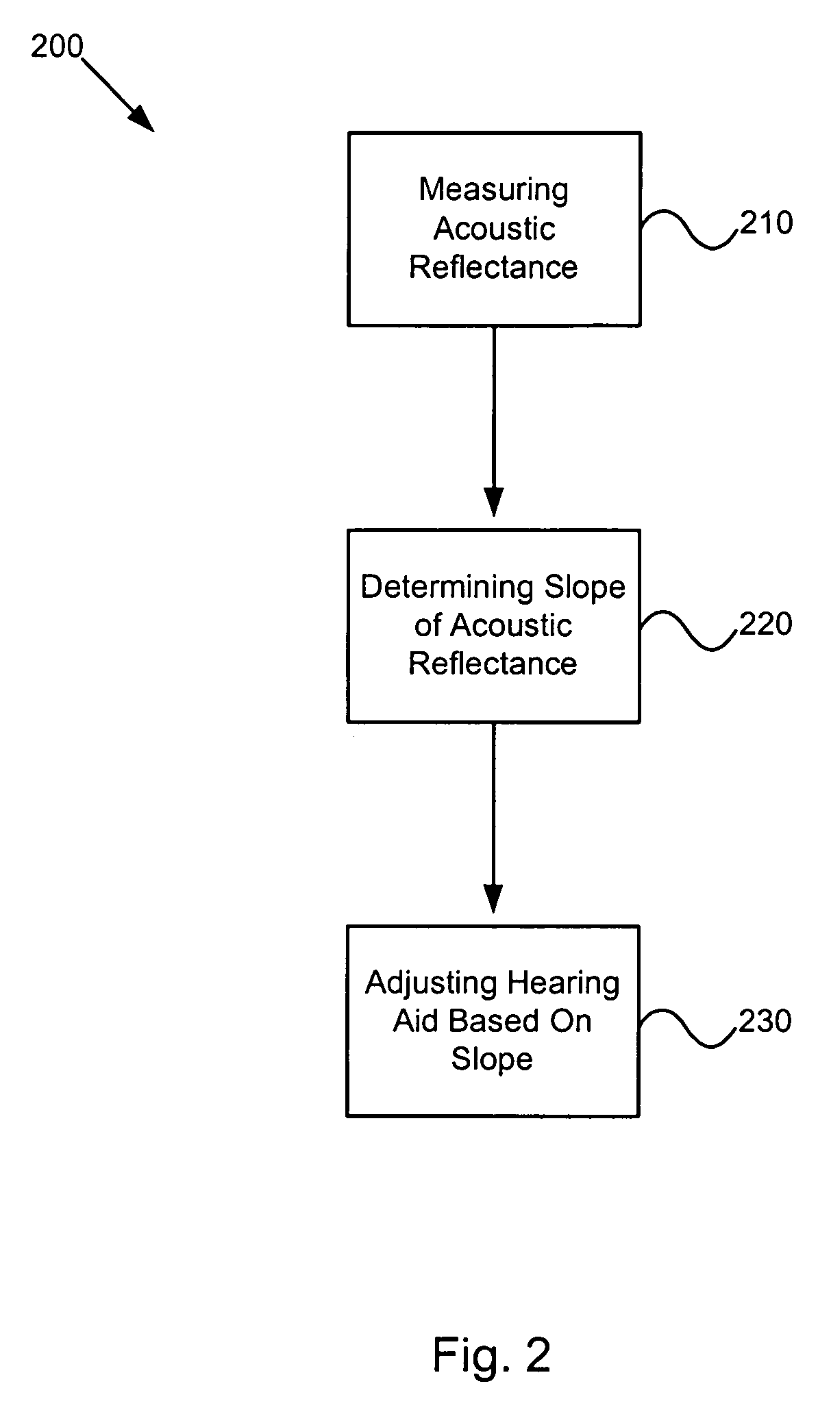
Method and system for automatically adjusting a hearing aid. The method includes measuring an acoustic reflectance associated with an ear canal as a function of an incident pressure and an acoustic frequency, processing information associated with the measured acoustic reflectance, determining a reflectance slope based on, at least, information associated with the measured acoustic reflectance, and adjusting, at least, one parameter associated with the hearing aid based on, at least, information associated with the reflectance slope. The reflectance slope is associated with a reflectance component varying with the incident pressure.

Description

CROSS-REFERENCES TO RELATED APPLICATIONS [0001] This application claims priority to U.S. Provisional No. 60 / 619,517, filed Oct. 15, 2004, incorporated by reference herein for all purposes.STATEMENT AS TO RIGHTS TO INVENTIONS MADE UNDER FEDERALLY SPONSORED RESEARCH OR DEVELOPMENT [0002] NOT APPLICABLE REFERENCE TO A “SEQUENCE LISTING,” A TABLE, OR A COMPUTER PROGRAM LISTING APPENDIX SUBMITTED ON A COMPACT DISK. [0003] NOT APPLICABLE BACKGROUND OF THE INVENTION [0004] The present invention relates generally to acoustic devices. More specifically, the invention provides a method and system for automatically adjusting acoustic devices based on acoustic reflectance. For example, the acoustic reflectance is a relationship between reflected waves and incident waves. Merely by way of example, the invention has been applied to hearing aids, but it would be recognized that the invention has a much broader range of applicability. [0005] Hearing aids have been widely used to compensate hearing ...

Claims


Application Information

Patent Timeline
Patent Type & Authority Applications(United States)
IPC IPC(8): H04R25/00
CPCH04R25/453H04R25/70
Inventor ALLEN, JONT B.JENG, PATRICIA S.
Owner MIMOSA ACOUSTICS
Why Eureka
Try Eureka