Method and apparatus for creating aerial panoramic photography

a technology of aerial panoramic photography and apparatus, applied in the field of aerial photography, can solve the problems of not yet being built, tower, skyscraper, golf course, etc., and is unable to fully appreciate, for example, the penthouse views of the property, and cannot be fully imagined

Inactive Publication Date: 2006-04-20
SEGAL MARK +1
View PDF4 Cites 33 Cited by
  • Summary
  • Abstract
  • Description
  • Claims
  • Application Information

AI Technical Summary

Benefits of technology

[0005] The present invention is an aerial photography apparatus that comprises a remote controlled piloted aircraft, a platform, a camera, and a remote wireless transmitter for operating and controlling the apparatus. The remote controlled piloted aircraft is attached to the top side of the platform. The camera is attached to the bottom side of the platform using a rigid member having a rotatable joint. The remote controlled piloted aircraft lifts and moves the apparatus to a desired location at a specific altitude above a particular property where the panoramic aerial photograph is to be taken. Depending upon the wind forces exerted upon th

Problems solved by technology

In most instances, however, the tower, skyscraper, golf course has not yet been built.
As a result, the prospective partner is unable to envision, for example, the penthouse views of the property, or fully appreciate the proposed design of a golf course or the design due to the blockage of trees and other landscape contours that are limiting the view from the ground.
Although this system worked, the results were less than perfect.
For example, the photographs were not always complete, or did not provide the proper views, thereby, requiring another flight and another series of photographs; the photographs did not always provide a complete view and required additional time and expense of splicing portions of multiple photograph

Method used


Image

  • Method and apparatus for creating aerial panoramic photography
  • Method and apparatus for creating aerial panoramic photography
  • Method and apparatus for creating aerial panoramic photography

Examples


Embodiment Construction

will be better understood with reference to the following figures:

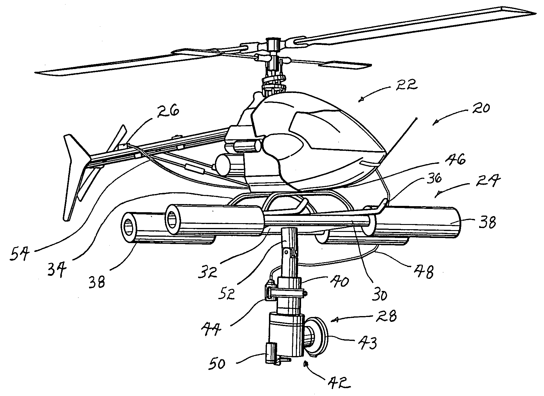
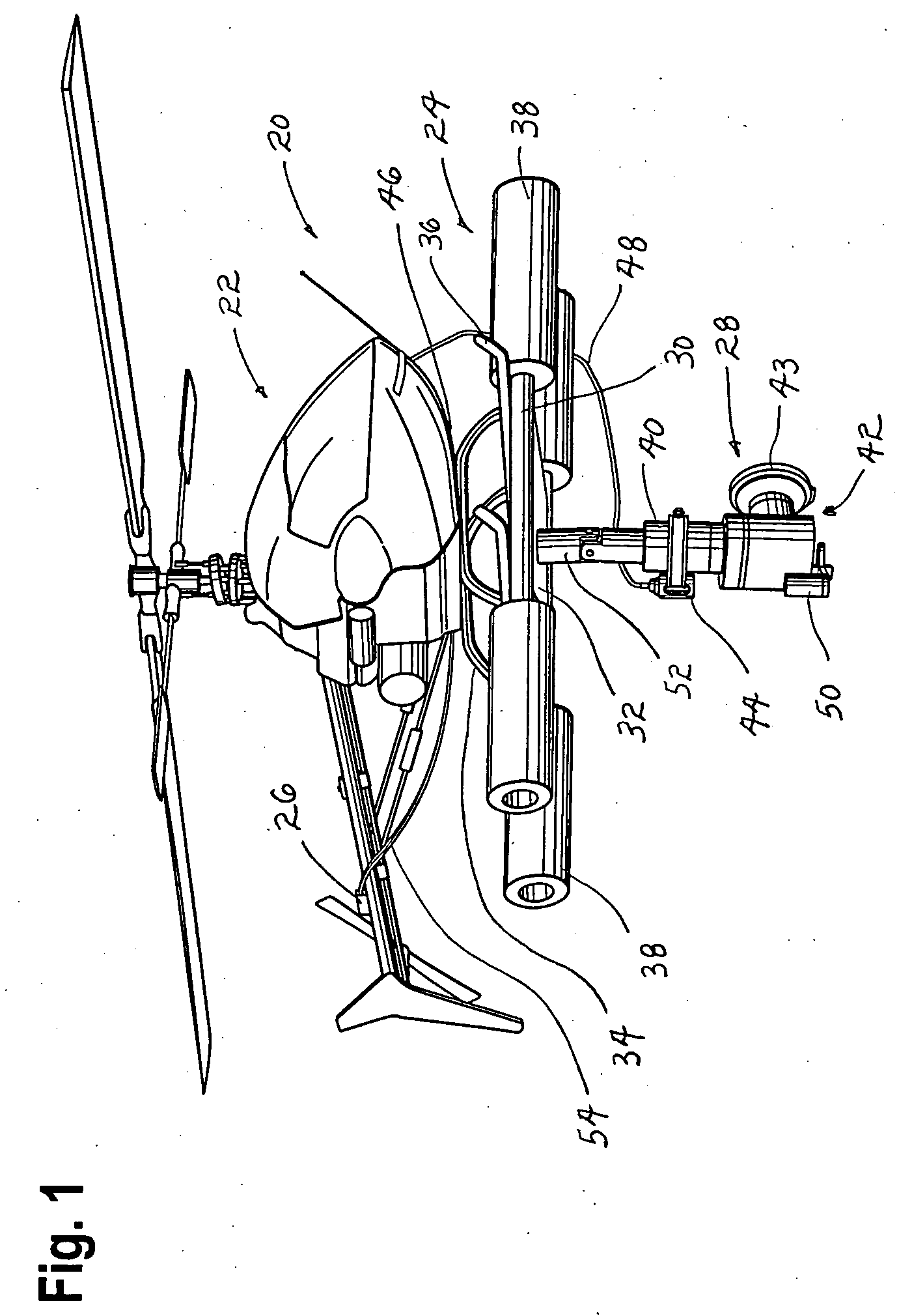
[0007]FIG. 1 is a perspective view of Applicant's invention and, in particular, illustrating the remote controlled piloted aircraft, the platform used for taking off and landing, and the camera equipment for creating the three hundred and sixty degree panoramic photography.

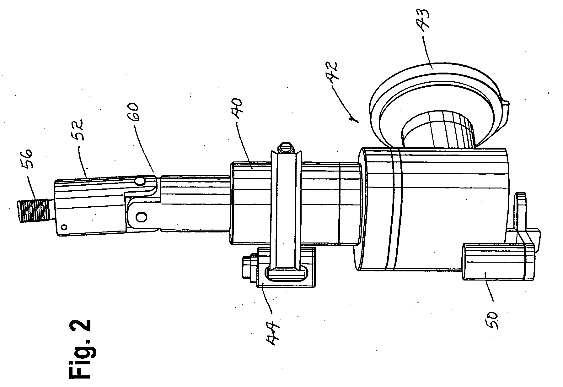
[0008]FIG. 2 is an enlarged side view, with portions removed, of the camera equipment and means for attaching the camera equipment to the platform.

[0009]FIG. 3 is a top view of a remote wireless transmitter for operating and controlling the piloted aircraft (i.e., the Propo is used for a large gas twin cylinder helicopter).

[0010]FIG. 4 is a top view of a remote wireless transmitter for operating and controlling the piloted aircraft (i.e., the T9 is used for a miniature single cylinder helicopter).

[0011]FIG. 5 is a top view of the remote wireless transmitter for operating and controlling the camera equipment.

[0012]FIG. 6 is a three hundred and s...


PUM


Abstract

An aerial photography apparatus that comprises a remote controlled piloted aircraft, a platform, a camera, and a remote wireless transmitter for operating and controlling the apparatus. The remote controlled piloted aircraft is attached to the top side of the platform. The camera is attached to the bottom side of the platform using a rigid member having a rotatable joint. The remote controlled piloted aircraft lifts and moves the apparatus to a desired location at a specific altitude above a particular property where the panoramic aerial photograph is to be taken. Depending upon the wind forces exerted upon the remote controlled piloted aircraft and the resulting orientation of the aircraft to maintain the camera at the desired location, the rotatable joint enables the gravitational weight of the camera to naturally gravitate to a vertical orientation or position relative to the ground. Alternatively, cushions in the platform or a suspension system may be used to achieve this position for the camera. A counterbalance weight is provided on the camera to counter the weight of the lens for maintaining the camera in a level balance while rotating through the three hundred and sixty degree rotation when creating the desired panoramic aerial photograph

Description

I. FIELD OF THE INVENTION [0001] The present invention relates to aerial photography and, more particularly, to three hundred and sixty degree aerial panoramic photography taken at varying altitudes using a remote controlled piloted aircraft. II. DESCRIPTION OF THE PRIOR ART [0002] Many architects and developers of residential or commercial towers and skyscrapers, of parks, golf courses, and the like have come to realize that there is a value in providing aerial views of their property and the surrounding views. This is especially true during the planning, preconstruction, and / or presales activities. During this time, the architects and developers are typically seeking funding, advance sales, or other forms of money and support from a prospective partner or purchaser. In most instances, however, the tower, skyscraper, golf course has not yet been built. As a result, the prospective partner is unable to envision, for example, the penthouse views of the property, or fully appreciate t...

Claims


Application Information

Patent Timeline
IPC IPC(8): G03B39/00
CPCA63H27/12A63H30/04G03B15/006G03B37/00
Inventor SEGAL, MARKJONES, JEFF
Owner SEGAL MARK
Why Eureka
Try Eureka