Memory device having a hiding and swing plug and method for hiding and swing a plug thereof

Inactive Publication Date: 2006-04-20
TUL CORP
4 Cites 27 Cited by

AI-Extracted Technical Summary

Problems solved by technology

The USB plugs of these kinds of devices are usually quite fragile, and once damaged they can no longer be connected to the computers via a USB receptacle.
However, because the small size of the cover, it can be easily lost sometimes.
And due to different sizes of the memory sticks it is sometimes difficult (and occasionally not possible) to insert the stick into the USB port on the computer.
However, none of these de...

Method used

[0029] When the USB plug (40) is pushed out of the body (10) by the sliding set (20), it will then be able to swing either up or down, or from left to right (relative to the user's point of view) (See FIG. 3). If this is the case, even if due to some specific requirement or design of the shape of the memory device, as it could be thicker than a notebook, the user ...

Benefits of technology

[0009] It is an object of the present invention to provide a new way of thinking and designing a portable memory device that does not need a cover to be put over a USB plug when not in use, and the USB plug (or the ...

Abstract

The mean for the universal serial bus hide and swing, its body inside have a sliding unit its head pivot to establish on can swing from as of deal with USB, and a memory to equip the electricity conjunction in deal with USB. The USB can conceal in the body, or along with the sliding unit to swing after being moved the indentation of the body.

Application Domain

Technology Topic

Image

  • Memory device having a hiding and swing plug and method for hiding and swing a plug thereof
  • Memory device having a hiding and swing plug and method for hiding and swing a plug thereof
  • Memory device having a hiding and swing plug and method for hiding and swing a plug thereof

Examples

  • Experimental program(1)

Example

[0021] According to the design of this particular device, the explanation of its construction with illustrations is as the following.
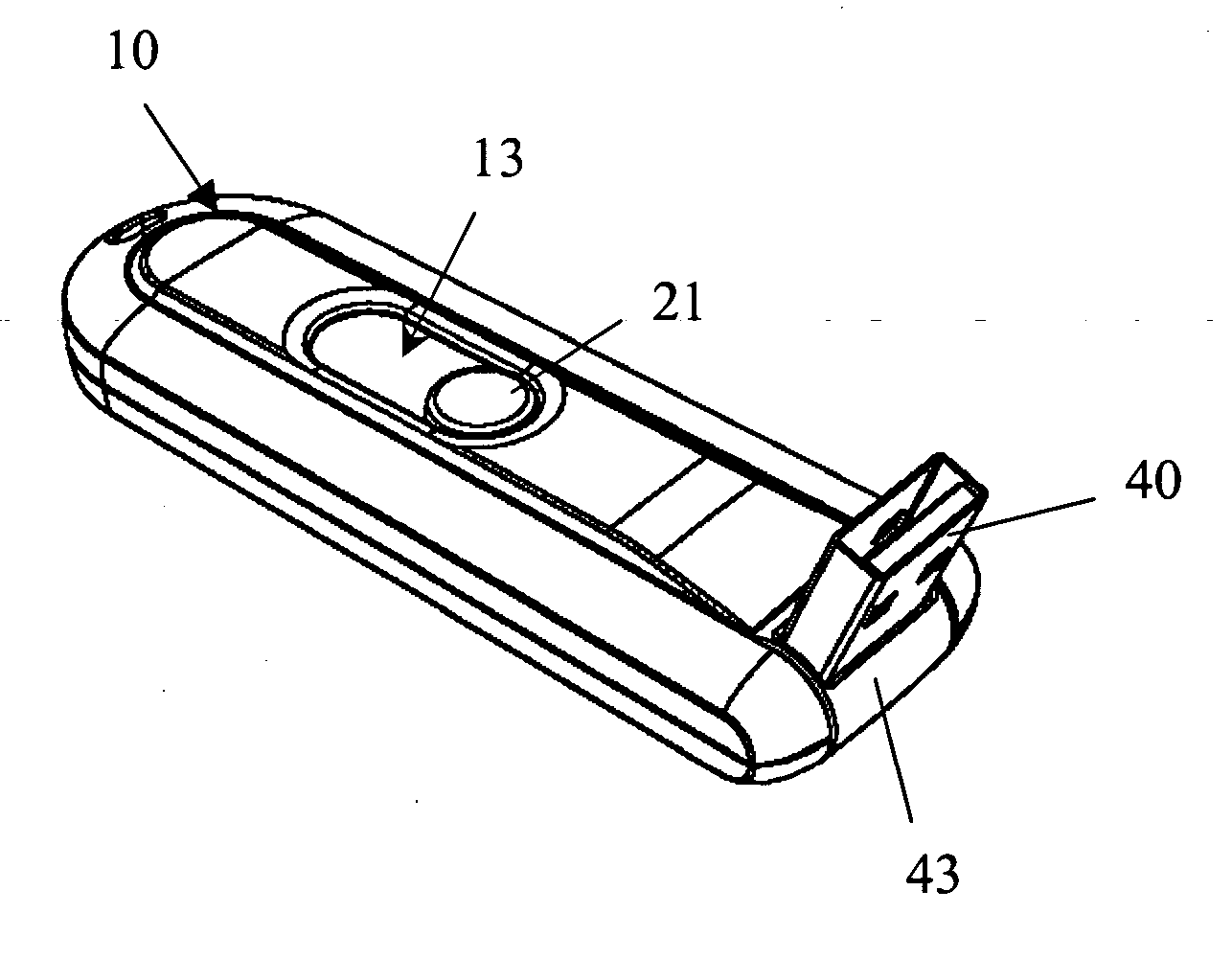
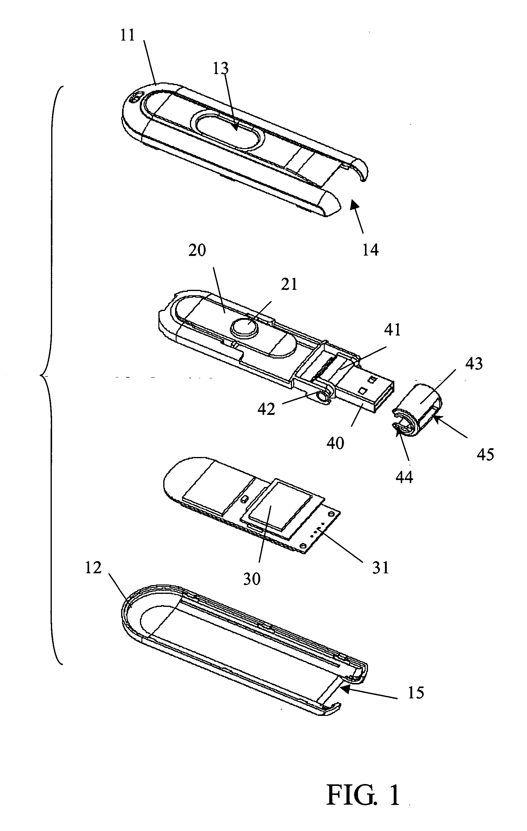
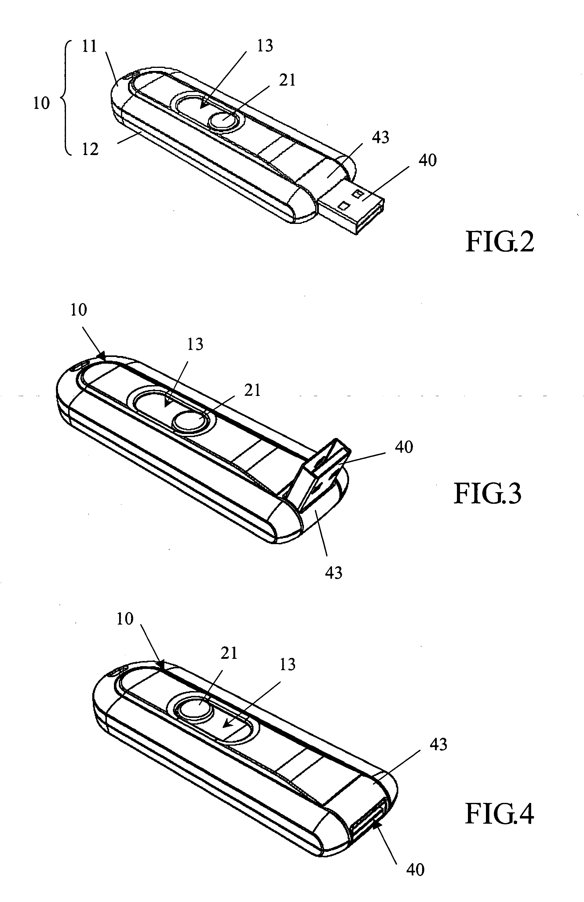
[0022] The main components of the device are (See FIG. 1 and FIG. 2): two halves of lengthened shells, respectively named as upper shell (11) and the bottom shell (12), make up the body (10). Alongside the edges of either the upper shell (11) or the bottom shell (12), a sliding set (20) is installed, and having the elongated slot (13) constructed on the upper shell (11) together to form the sliding unit (See FIG. 2 and FIG. 4 for its schematic drawings). The sliding set (20) has a handle (21), and the elongated slot (13) can be used for the handle (21) to be accessed. The body (10) itself has an opening at one end.
[0023] The sliding set (20) is on the inside of the upper shell (11) with the handle (21) pointing upwards and out through the elongated slot (13), hence the movement of the sliding set (20) can be controlled from the top by the handle i.e. outside of the upper shell (11).
[0024] The printed circuit board (PCB) (30) accommodated inside the body (10) is fixed onto the sliding set (20). At least one flash memory device is installed as a part of the overall memory device. The USB plug (40) is connected electrically to the PCB (30). FIG. 1 shows how the terminal (31) can be connected through electronic signal communicating wires to the USB plug (40) when constructed underneath the sliding set (20) and therefore the PCB (30) and the sliding set (20) will move simultaneously. Another way of constructing it is to have the PCB (30) fixed onto the bottom half of the body's shell (12), and so it will not move with the motion of the sliding set (20). In this case, longer signal cables will be needed to join the USB plug (40) and the PCB (30) together.
[0025] The USB plug (40) is designed to be swing-able and is joined (pivoted) electrically to the PCB (30) by a swing-able plug unit. As shown by FIG. 1, the swing-able plug unit is consisting of a hinge (42) and a swing part (41), the hinge (42) is pivoted at the end of the sliding set (20) while the swing part (41) is connected to the hinge (42) as well, hence the USB plug (40) can swing freely from side to side. This invention herein disclosed has been described by means of specific embodiments; numerous modifications and variations could be made. For example (the figure omitted) the hinge (42) is fixes to the sliding set (20), and the swing part (41) is attaching the USB plug (40). The swing part (41) which interior has the hole pivoted in the hinge (42) to maintenance relative motions each other.
[0026] As shown by FIG. 1, both the upper shell (11) and the bottom shell (12) have an indentation (14) and (15) respectively. When the two shells are closed, the indentation will form the opening of the body (10). There is another cover (43) having an axial opening (44) on each side, and a hole (45) that is slightly larger than the plug (40), which will allow the USB plug (40) to pass through. The width of this cover (45) is shorter than the width of the indentation (14) of the upper shell and the indentation (15) of the bottom shell, this will just cover the swing part (41) and be pivoted at the opening of the body (10). When the upper and bottom shells (11 and 12) are closed the cover (43) will be locked into position by the opening created by the two indentations (14 and 15) yet able to move in a swinging motion and as shown by FIGS. 2 and 4, the USB plug (40) can move in and out through the hole (45) on the cover (43). Under all circumstances, the PCB (30) and the USB plug (40) will always be connected by signal communicating wires.
[0027] No matter how the manufacturer decides to make the handle (21), either as an individual piece which will later be joined together with the sliding set (20) or make the handle (21) and the sliding set (20) as one piece of component, after assembled the sliding set and the handle (20 and 21) will be physically mounted together. And also disregard to whether the manufacturer wants to design the elongated slot (13) on the upper shell (11) or on the bottom shell (12), the idea of using the handle (21) to control the sliding set (20) to be pushed out is the same. Even if the elongated slot (13) is designed on the side of the upper or the bottom shell (11 and 12) in order for the handle to push the sliding set (20) from the side of the body (10), it is still equivalent to the design of this particular memory device. Another possible approach to designing the device is to divide the body (10) up into two pieces (the front and back halves) and have them rather sliding, stretching against each other as a relative motion. For example, when the front half and the back half of the body are pulled away horizontally from each other, the USB plug (40) will be hidden inside, and when the two halves are pushed towards each other, the USB plug (40) will be pushed out from the front half of the body.
[0028] In an actual event of using the device, the handle (21) on the outside of the body (10), the sliding set (20) and the USB plug (40) will move simultaneously. In other words, the user can use the handle (21) to push or pull the sliding set (20) and hence move the USB plug (40) in or out of the body (10) through the hole (45) at the front. When the USB plug (40) is pulled back into the body (10) it will be protected by the body (10) itself from colliding, scratching, and other possible external damages. (See FIGS. 2 and 4)
[0029] When the USB plug (40) is pushed out of the body (10) by the sliding set (20), it will then be able to swing either up or down, or from left to right (relative to the user's point of view) (See FIG. 3). If this is the case, even if due to some specific requirement or design of the shape of the memory device, as it could be thicker than a notebook, the user only has to move the USB plug (40) once inserted into the computer in order to avoid adjusting the height of the notebook. The plug of this memory device can also be squeezed adjacent to other computer accessories that may also need to be inserted into a USB receptacle such as a USB mouse, a USB keyboard et cetera. Thus, making it fairly practical and convenient.
[0030] The above-mentioned embodiments give evidence of the operability of this invention in details. However, if anyone masters this technology and invents a similar system that has difference either in appearance or in details, will be held legal responsibility of trespassing the originality and patent of this invention. Although certain preferred embodiment of the present invention has been shown and described in detail, it should be understood that various changes and modification might be made therein without departing from the scope of the appended claims.

PUM

no PUM

Description & Claims & Application Information

We can also present the details of the Description, Claims and Application information to help users get a comprehensive understanding of the technical details of the patent, such as background art, summary of invention, brief description of drawings, description of embodiments, and other original content. On the other hand, users can also determine the specific scope of protection of the technology through the list of claims; as well as understand the changes in the life cycle of the technology with the presentation of the patent timeline. Login to view more.

Similar technology patents

Vehicle door frame sealing strip structure and automobile

PendingCN114789647AIncrease compatibilityImprove appearance performanceEngine sealsVehicle sealing arrangementsLap jointCar door
Owner:阿维塔科技(重庆)有限公司

Rust-proof gate valve with high sealing performance

PendingCN113606357ANot easy to slideIncrease compatibilitySpindle sealingsPlug valvesEngineeringGate valve
Owner:铜陵荣景科技有限公司

Classification and recommendation of technical efficacy words

Why Eureka
Try Eureka