Laser pulse position monitor for scanned laser eye surgery systems

a laser eye surgery and laser pulse technology, applied in the field of laser pulse position monitor for scanned laser eye surgery systems, can solve the problems of not being able to achieve the desired tissue ablation pattern, using such movable beam systems, and complicating certain aspects of treatment protocols, so as to achieve the effect of reliably and accurately determining the position and/or light energy of the puls

Inactive Publication Date: 2006-04-20
AMO MFG USA INC
View PDF14 Cites 30 Cited by
  • Summary
  • Abstract
  • Description
  • Claims
  • Application Information

AI Technical Summary

Benefits of technology

This patent describes better ways to measure how far out light has traveled by looking at its electrical properties. These new methods can work very quickly and have been tested over a wide range of frequencies. They also make it possible to determine things like the color of individual photons of light. Overall, this makes it easier to get accurate measurements no matter what kind of light we're trying to analyze.

Problems solved by technology

This patent describes improving devices, systems, and methods for identifying the position of laser beams used in refractive eye surgery. Current technology relies upon charged coupling device (CCDs) and pixels to measure the position of moving laser beams, but this method has limitations in terms of cost and speed. Additionally, some applications require higher precision than others. There is a technical problem in developing better tools to quickly and accurately identify the position of pulsed laser beams in real-time without compromising the quality and efficiency of the laser eye surgery process.

Method used


Image

  • Laser pulse position monitor for scanned laser eye surgery systems
  • Laser pulse position monitor for scanned laser eye surgery systems
  • Laser pulse position monitor for scanned laser eye surgery systems

Examples


Embodiment Construction

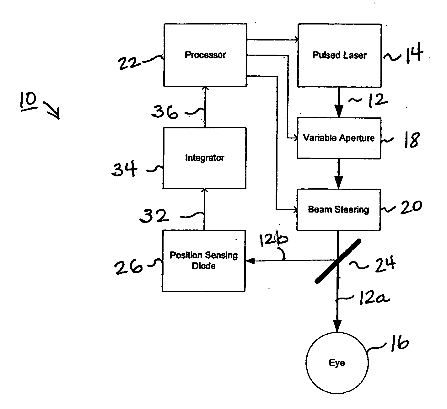
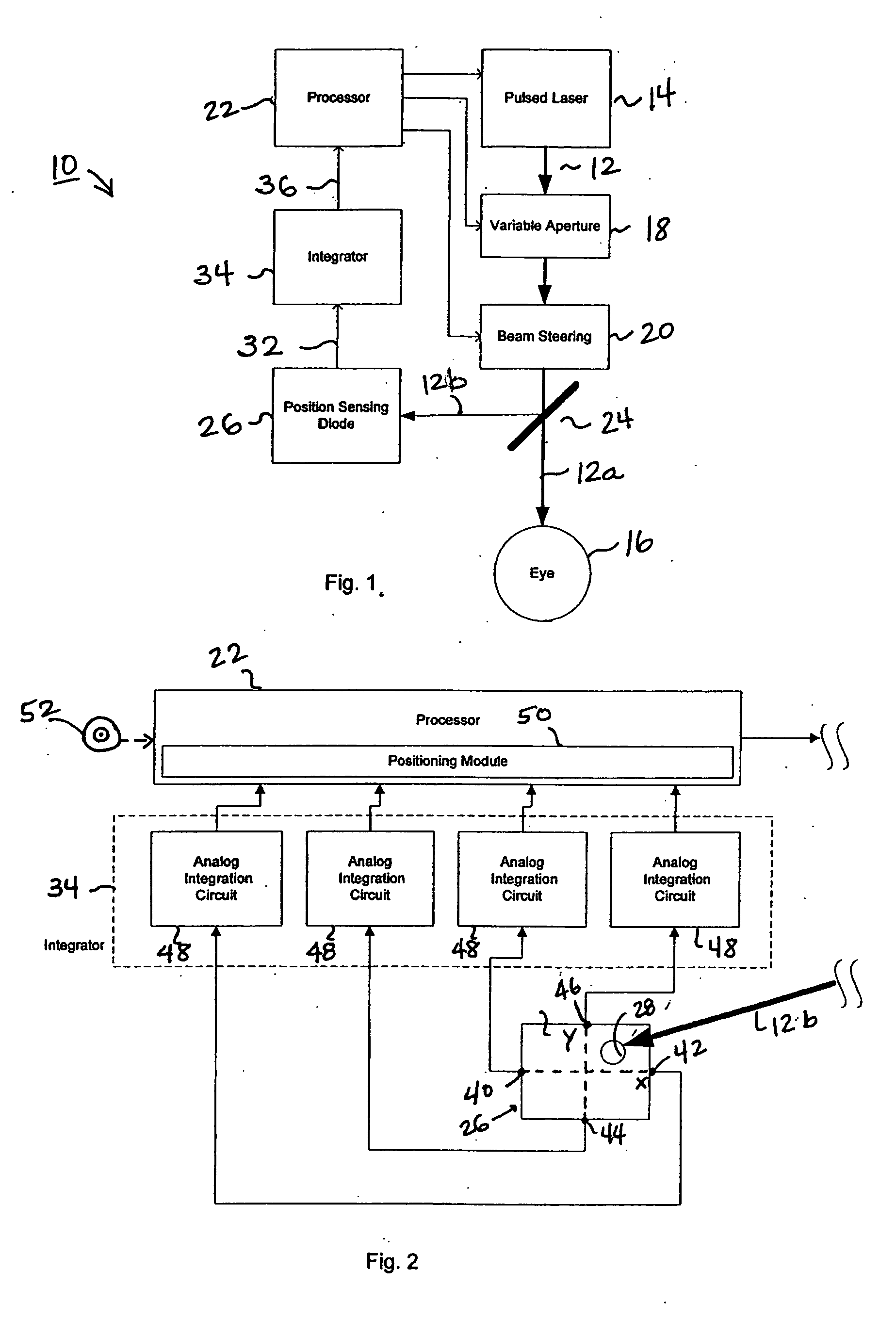
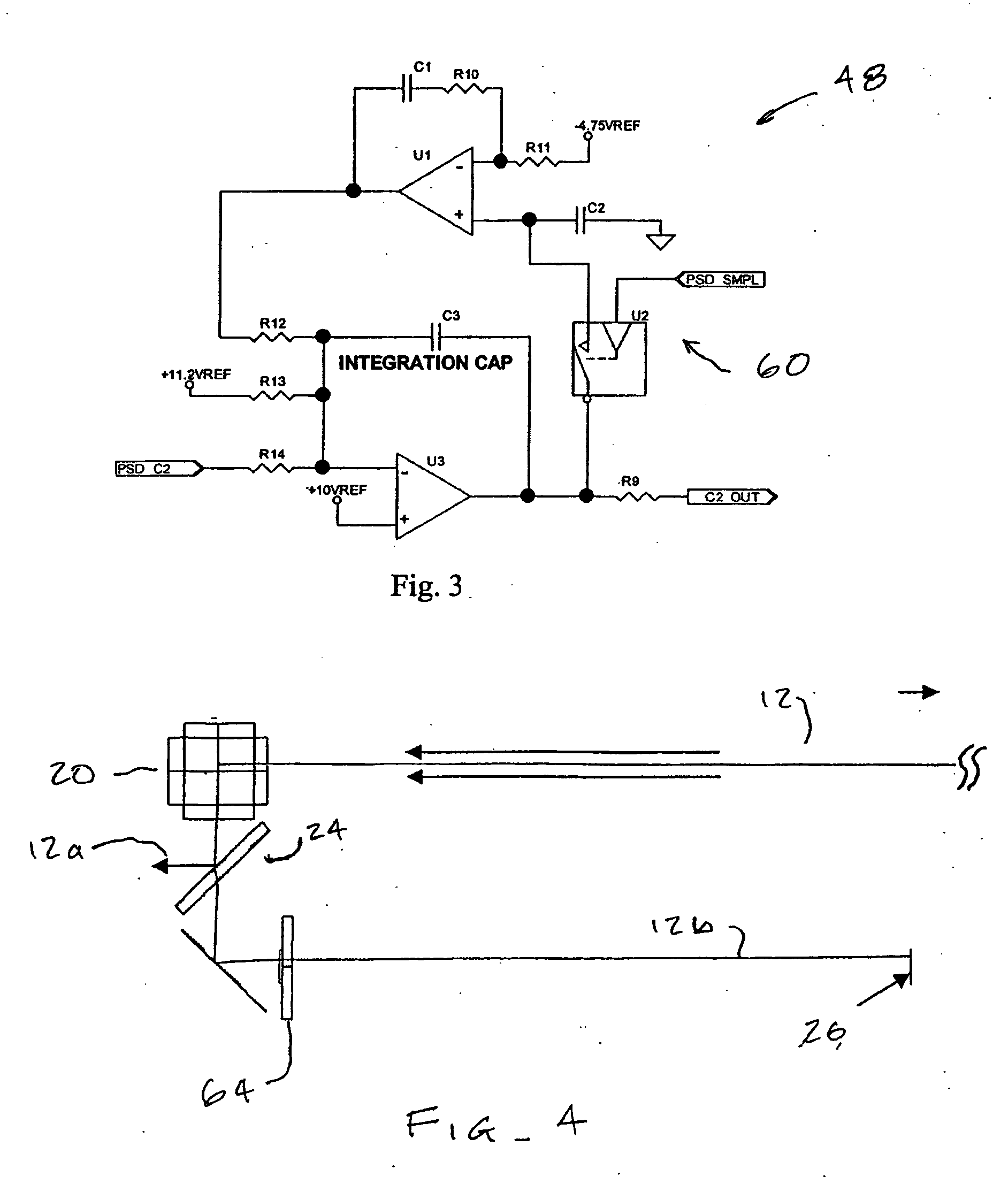
[0030] The present invention generally provides improved devices, systems, and methods for measuring light beams. The systems of the present invention will generally include position sensing diode (PSD) silicon photodiodes that provide an analog output. As the devices, systems, and methods of the invention allow the accurate use of position sensing diodes for both wavelengths which were known to be compatible with PSDs and for wavelengths which were previously thought to be incompatible with these analog devices, the techniques of the invention may expand the use of these accurate, simple, and low-cost structures. By use of the inventions described herein, position sensing diodes may be used to accurately measure position and / or light energy of pulsed beams having wavelengths of less than 300 nm, the beams optionally having wavelengths of 220 nm or less, the beams often having wavelengths of less than 200 nm, and in many cases the beams having wavelengths of 196 nm or less. Hence, t...


PUM


Abstract

Devices, systems, and methods for measuring and determining positions of light energy having wavelengths of less than (as well as equal to or greater than) 200 nm, and are particularly well suited for measuring pulsed light at ultraviolet and other wavelengths using position sensing diode (PSD) technology. An integrator may sum a total charge of a signal from the PSD. Correlations between a distribution of integrated charges among electrodes of the PSD may be non-linear, and may benefit from adjustment for different overall pulse light quantities and/or spot sizes.

Description


Claims


Application Information

Patent Timeline
Owner AMO MFG USA INC
Why Eureka
Try Eureka