Laser ablation method and apparatus having a feedback loop and control unit

a technology of feedback loop and control unit, applied in the field of laser ablation system and method, can solve the problems of ultra-short pulse, otherwise impossible or impractical to implement with other technologies, and achieve the effect of optimizing the ablation

Inactive Publication Date: 2006-04-20
UNIV OF CENT FLORIDA RES FOUND INC +1
View PDF99 Cites 126 Cited by
  • Summary
  • Abstract
  • Description
  • Claims
  • Application Information

AI Technical Summary

Benefits of technology

[0009] This invention improves the existing laser ablation systems and methods by providing a feedback mechanism that measures an indicative property of an ablation target or an indicative property of the pulsed laser projected on the ablation target. The feedback mechanism generates a feedback signal according to the measured indicative property, and sends the feedback signal to a control unit. The control unit then adjusts an output parameter of the pulsed laser according to the feedback signal to optimize ablation effect.

Problems solved by technology

Numerous applications of ultrashort pulses have been developed that would be otherwise impossible or impractical to implement with other technologies.

Method used


Image

  • Laser ablation method and apparatus having a feedback loop and control unit
  • Laser ablation method and apparatus having a feedback loop and control unit
  • Laser ablation method and apparatus having a feedback loop and control unit

Examples


Embodiment Construction

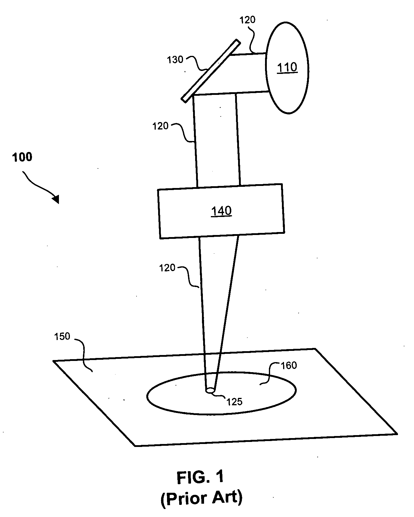
[0029]FIG. 1 is a schematic illustration of a conventional laser ablation system. Laser ablation system 100 has laser device 110 for generating laser beam 120, which is reflected by mirror 130, processed by an optical device 140 (typically a lens system) and focused on ablation target 150. The focused laser beam 120 projects laser spot 125 in ablation field 160, which is a part of ablation target 150 intended to be ablated. For a given ablation spot, laser ablation process uses the focused laser beam 120 to remove a surface material on the small spot where the laser beam 120 is projected and focused on to form laser spot 125.

[0030] The ablation point and depth are controlled via moving mirror 130, which is typically done through a galvanometer (not shown), a device for detecting or measuring a small electric current by movements of a magnetic needle or of a coil in a magnetic field. Commercial galvanometers are available which use an electric current through a coil to induce precis...


PUM


Abstract

A laser ablation method and apparatus uses a laser device to generate a pulsed laser using a laser device and to project the pulsed laser onto an ablation target to be ablated. A probe is then used to measure an indicative property of the ablation target or of the pulsed laser projected on the ablation target. A control loop is used to optimize ablation effect by generating a feedback signal according to the measured indicative property, sending the feedback signal to a control unit, and adjusting an output parameter of the pulsed laser according to the feedback signal. The measured indicative property may be a size of the laser beam spot or a material composition. The ablation, the feedback and the adjustment may be performed dynamically.

Description

CROSS-REFERENCE TO RELATED APPLICATIONS [0001] This application is a continuation-in-part of U.S. patent applications Ser. No. 10 / 849,585, filed May 19, 2004 (Docket No. ABI-1042), entitled “Scanned Small Spot Ablation with a High-Repetition-Rate Technical Field of the Invention”; Ser. No. 10 / 916,367, filed Aug. 11, 2004 (Docket No. ABI-1043), entitled “Controlling Pulse Energy of an Optical Amplifier by Controlling Pump Diode Current”; Ser. No. 10 / 916,368, filed Aug. 11, 2004 (Docket No. ABI-1044), entitled “Pulse Energy Adjustment for Changes in Ablation Spot Size”; Ser. No. 10 / 916,365, filed Aug. 11, 2004 (Docket No. ABI-1045), entitled “Ablative Material Removal with a Preset Removal Rate or Volume or Depth”; Ser. No. 10 / 850,325, filed May 19, 2004 (Docket No. ABI-1047), entitled “Controlling Pulse Energy of an Optical Amplifier by Controlling Pump Diode Current”; Ser. No. 10 / 849,586, filed May 19, 2004 (Docket No. ABI-1048), entitled “Altering the Emission of an Ablation Beam f...

Claims


Application Information

Patent Timeline
Patent Type & Authority Applications(United States)
IPC IPC(8): A61B18/18
CPCA61B18/20A61B2018/00636A61B2017/00057
Inventor DELFYETT, PETERSTOLTZ, RICHARD
Owner UNIV OF CENT FLORIDA RES FOUND INC
Why Eureka
Try Eureka