
Laminar flow meter or controller

a flow meter and controller technology, applied in the direction of liquid/fluent solid measurement, process and machine control, instruments, etc., can solve the problems of accuracy attributed to a given design, reduce the dynamic pressure expression, and facilitate effective “tuning” the design of the instrumen

Active Publication Date: 2006-04-27
SIERRA INSTR
View PDF4 Cites 8 Cited by
  • Summary
  • Abstract
  • Description
  • Claims
  • Application Information

AI Technical Summary

Benefits of technology

[0043] To understand another feature or advantage of the present invention, we refer to Equation (2) above. In a perfect instrument, Equation (2) would be expressed as Q=[C / μ] [P1−P2] (i.e., the pressure drop, P1−P2, senses only the pressure drop across a laminar flow assembly having a perfect laminar flow). In practice, however, this perfect instrument is always contaminated with some errors associated with dynamic pressure effects.
[0044] In Equation (2), dynamic pressure effects are embodied in the expression [1 / (2A12)−1 / (2A22)−F]pQ2. The first two terms in this expression are the dynamic pressures, pV12 / 2 and pV22 / 2, at the inlet and outlet pressure ports, respectively, where V1 and V2 are the flow velocities at the upstream and downstream pressure ports, respectively. As more fully described in the previous explanation of Equation (2), the third term F, in this expression accounts for all permanent pressure losses between the inlet and outlet pressure ports, except for the pressure drop across the laminar flow assembly. For air at atmospheric pressure and room temperature, the dynamic pressure, pV12 / 2, at full-scale flow is approximately one-tenth of the pressure drop across the laminar flow assembly. At higher pressures this fraction is larger. In some known meters, the areas A1 and A2 are not equal and / or the flow path between pressure ports is tortuous. In such instruments, errors caused by pQ2 effects can be significant.
[0045] In a preferred variation of the invention, the areas are instead equal or nearly so. Such an approach reduces the previously mentioned dynamic pressure expression to −F pQ2. Furthermore, to minimize the factor F, the flow path between the pressure ports in the present invention may be made as smooth as is practicable. These measures combine to yield nearly linear Q vs P1−P2 performance from zero to full-scale flow for the instruments of the present invention. No know meter is believed to offer comparable performance.
[0046] As an alternative to the above approach, it is possible to reduce the dynamic pressure expression to nearly zero by either reducing the inlet area A1 sufficiently such that 1 / (2A12)−1 / (2A22)=F, or by adjusting any one or more of the three terms in the dynamic pressure expression such that the sum 1 / (2A12)−1 / (2A22)−F=O. This method facilitates effectively “tuning” the design of the instruments to nearly eliminate dynamic pressure effects.
[0047] Although the preferred embodiment of the present invention as more particularly described below may offer all of the benefits or advantages based on a combination of features as described above, the individual aspects noted may be regarded and claimed independently below or in any combination or permutation with the other features discussed herein. In addition, methodology as implicitly or explicitly disclosed—especially in connection with the systems described form part of the invention.

Problems solved by technology

The cost and accuracy attributed to a given design are, naturally, of importance to users of the instruments.

Method used


Image

  • Laminar flow meter or controller
  • Laminar flow meter or controller
  • Laminar flow meter or controller

Examples


example

[0098] As for the performance of the subject devices, FIG. 11 demonstrates a nearly linear relationship between the total flow rate, Q, and the pressure drop, P1−P2, for the embodiment of the mass flow controller and element stack shown in FIGS. 2 and 3. Comparable performance should be manifested in other configurations built according to the same principles.

[0099] The data shown in FIG. 11 is for air at 20 degrees centigrade and one atmosphere pressure. The subject laminar flow assembly was constructed with an internal diameter of 0.626 inches, an external diameter of 1.110 inches in a flow body with an internal bore diameter of 1.275 inches. Each closed slice had a thickness of 0.006. Open slices were provided that defined three rectangular laminar flow channels, each with a height, a, of 0.0030±0.0002 inches, a width, b, of 0.542±0.005 inches, and an average length, L, of 0.265 inches. The flow areas A1 and A2 of the bore of the laminar flow assembly and the annular exit channe...


PUM


Abstract

Volumetric flow meters, volumetric flow controllers, mass flow meters, and mass flow controllers using a transverse laminar flow assembly are described. The flow assembly may be constructed from a plurality of open and / or closed slices or layers stacked upon one another and held together in compression by through bolts or another means. Meter or flow controller accuracy may be aided by use of flow conditioning features preceding an axial bore of the transverse flow assembly including one or more of a deflector, filter and nozzle.

Description

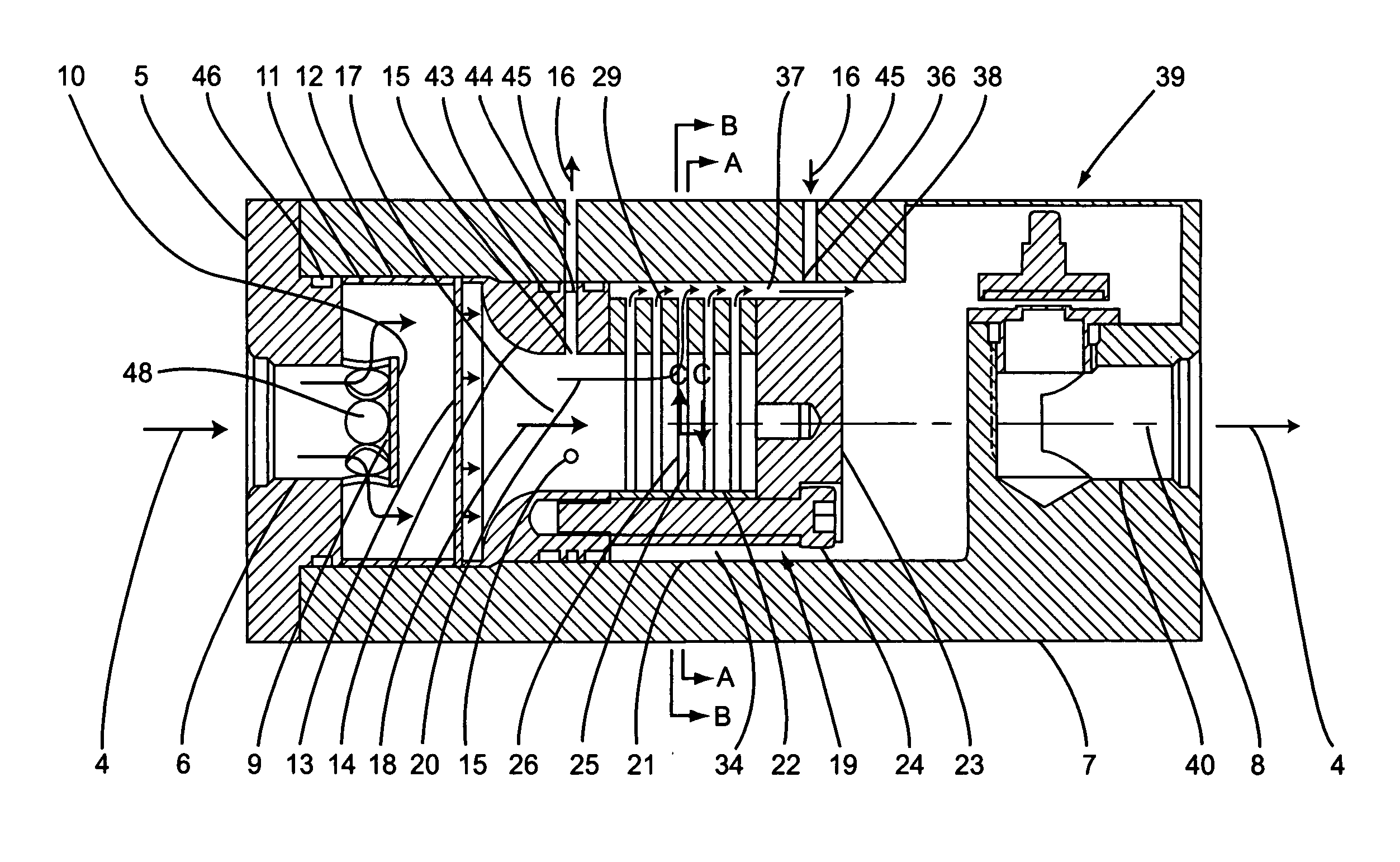
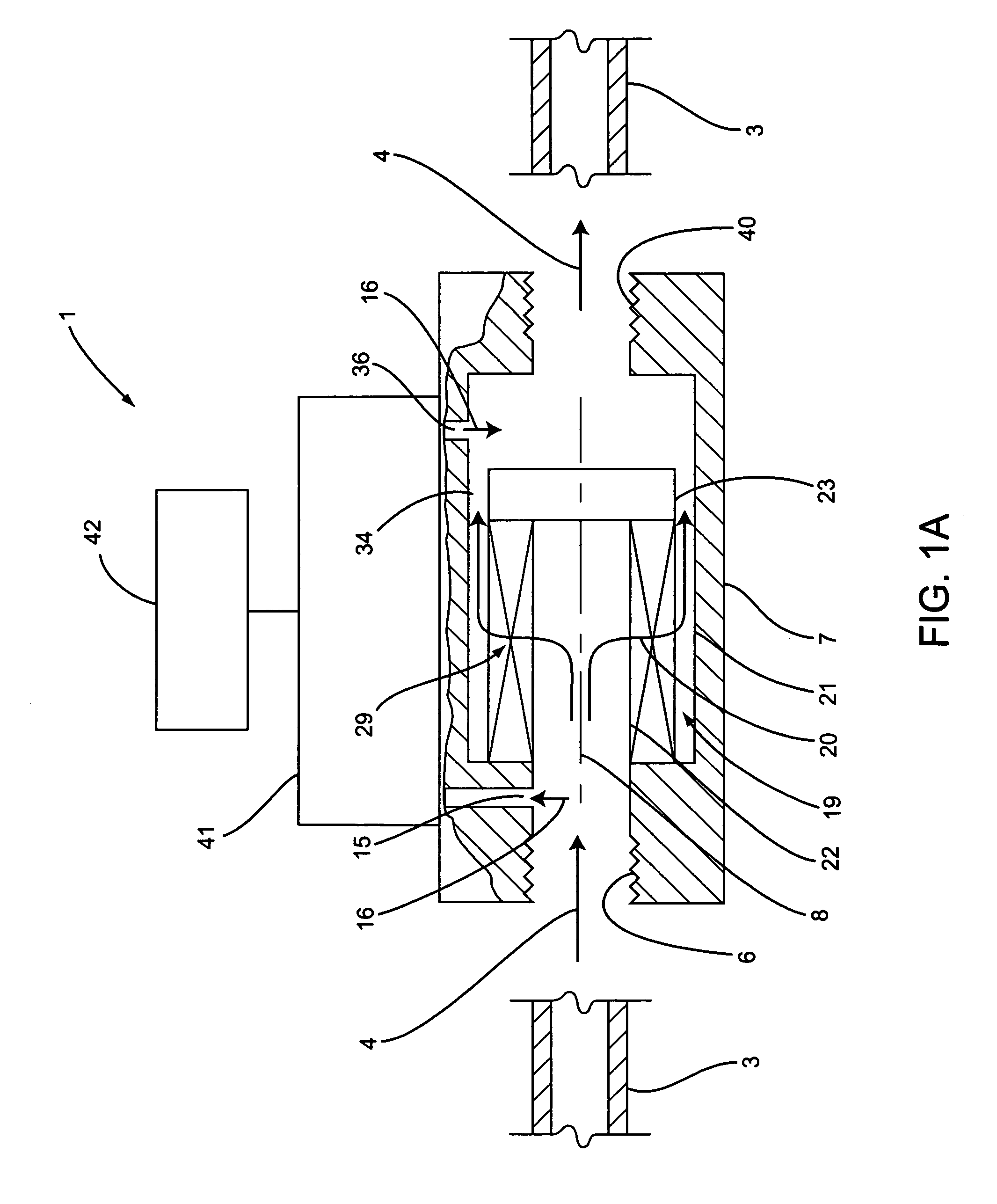
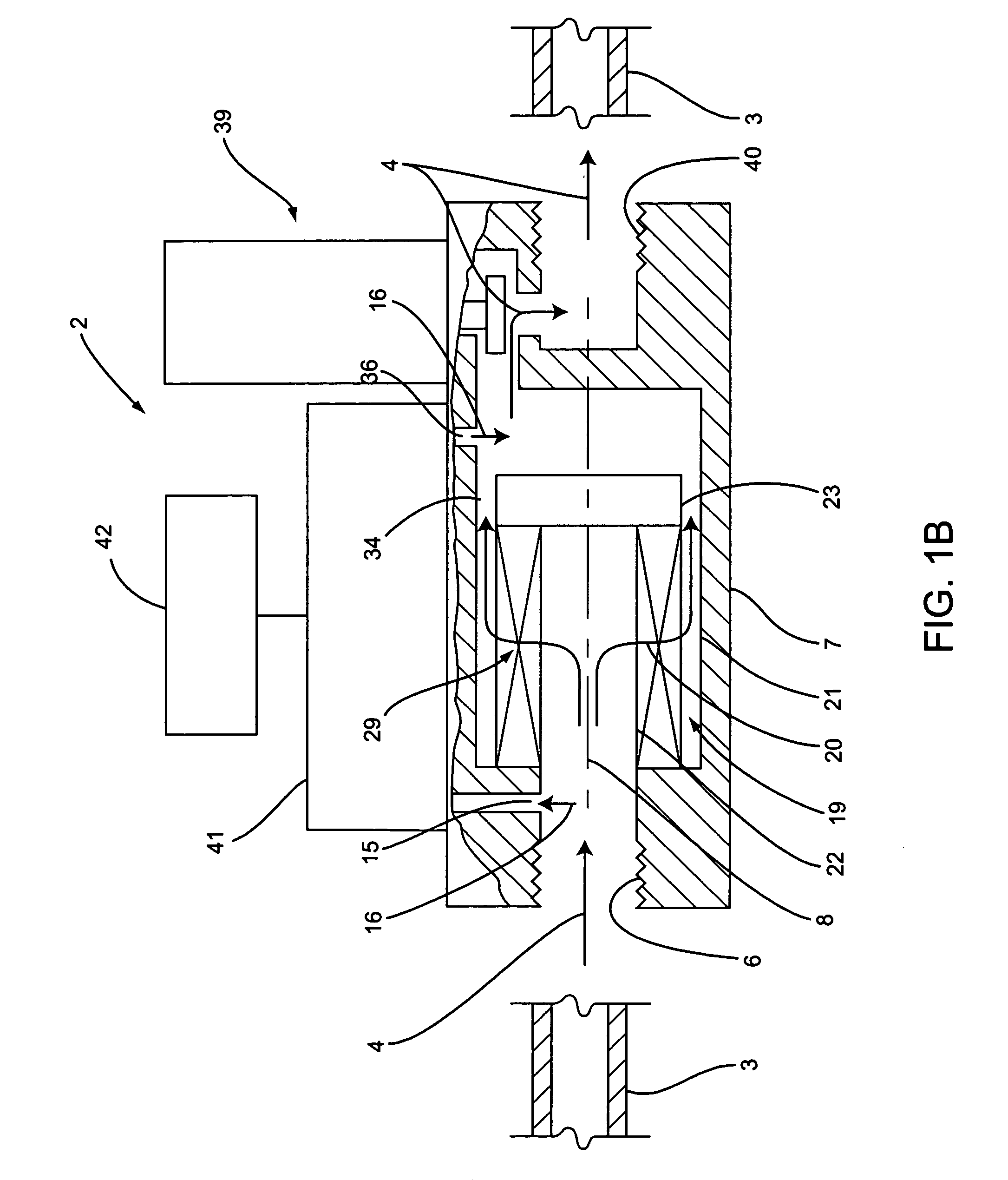
FIELD OF THE INVENTION [0001] This invention relates to volumetric flow meters, volumetric flow controllers, mass flow meters, and mass flow controllers (hereinafter collectively, “instruments”) using a laminar flow assembly, particularly regarding their decreased cost of manufacture and increased accuracy. BACKGROUND OF THE INVENTION [0002] One class of flow meter and flow controller employs a body configured to provide for laminar fluid flow therethrough. Flowing fluid from a conduit system enters the inlet process connection of the meter flow body, passes through a laminar flow assembly, exits through an outlet process connection of the flow body, and continues its flow within the conduit system. In passing through the laminar flow assembly, the fluid creates a pressure drop, P1−P2, between an inlet pressure port and the outlet pressure port arranged on opposite sides of the laminar flow assembly that is sensed by a differential pressure sensor. Volumetric flow meters based upon ...

Claims


Application Information

Patent Timeline
Patent Type & Authority Applications(United States)
IPC IPC(8): G01F1/37
CPCG01F1/36G01F1/40G05D7/0635
Inventor OLIN, JOHN GEORGESMITHERMAN, JOHN PAUL
Owner SIERRA INSTR
Learn More