Control Valve Device With A Float Position

A floating position, control valve technology, applied in the direction of fluid pressure actuation device, servo motor, servo meter circuit, etc., to achieve the effect of simple structure and consumption

Active Publication Date: 2015-08-26
LINDE HYDRAULICS
View PDF8 Cites 4 Cited by
  • Summary
  • Abstract
  • Description
  • Claims
  • Application Information

AI Technical Summary

Problems solved by technology

Depending on the design of the control valve, a high dynamic pressure and thus a high counter pressure can develop for the pressure medium flowing into the container via the control valve in the raised position of the hydraulic cylinder. The corresponding energy loss is caused during the ascending operation, which in turn causes the corresponding power loss

Method used


Image

  • Control Valve Device With A Float Position
  • Control Valve Device With A Float Position
  • Control Valve Device With A Float Position

Examples


Embodiment Construction

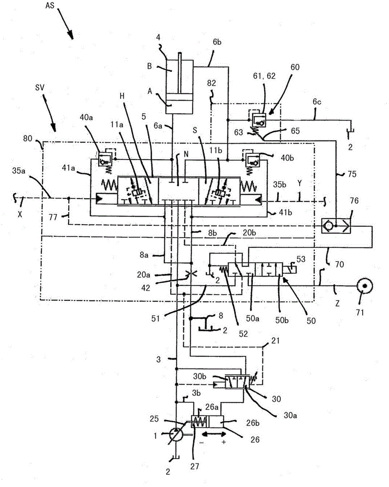
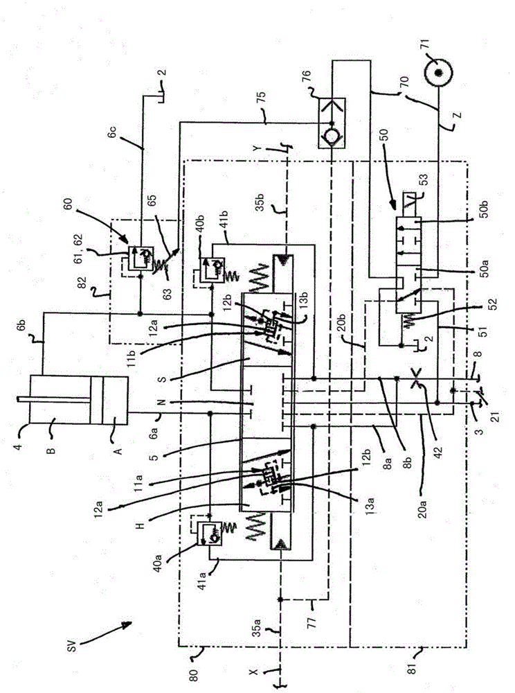
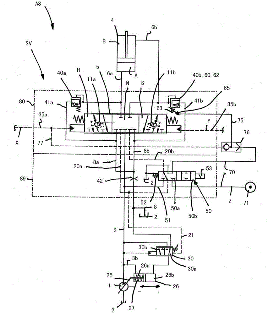
[0034] figure 1 A circuit diagram of a load-sensitively regulated drive system AS of a mobile work machine, for example in the form of an excavator or a wheeled loader, with the control valve arrangement SV according to the invention is shown.

[0035] The drive system AS comprises a pump 1 adjustable in delivery volume, which, in the exemplary embodiment shown, operates in an open circuit with an input side connected to a container 2 and an output side into a delivery line 3 , a plurality of consumers Connect to the delivery line. In the exemplary embodiment shown, a consumer in the form of a double-acting hydraulic cylinder 4 is shown, for the control of which a control valve arrangement SV according to the invention is provided.

[0036] The control valve arrangement SV comprises a control valve 5 that is throttled in an intermediate position. The hydraulic cylinder 4 configured as a reciprocating cylinder that raises and lowers a boom of a work machine has an ascending s...


PUM


Abstract

The invention relates to a control valve device used for controlling a double-acting hydraulic pressure cylinder of a mobile operation machine. The control valve device includes a control valve connected to a conveying pipeline, a container pipeline, an ascending pipeline and a descending pipeline of a pump. The control valve has a middle position, an ascending position and a descending position. The control valve device has a floating position. When the control valve is moved to the descending position, the ascending pipeline is connected with the container pipeline and the pump is connected with a descending side and switching meets failure. A release valve is arranged, so that the descending side can bypass the control valve to connect with the container and the descending side can be connected with the container in the floating position. When the control valve moves to the ascending position during ascending operation, the conveying pipeline is connected with the ascending pipeline and the descending side is enabled to connect with the container by the aid of the release valve during ascending operation, so that the descending pipeline is connected with the container through the release valve and pressure medium flow from the descending side flows to the container via the release valve.

Description

technical field [0001] The invention relates to a control valve arrangement for controlling a double-acting hydraulic cylinder of a mobile work machine, wherein the control valve arrangement comprises a control valve throttled in an intermediate position, which control valve is connected to the delivery line of a pump , the container line, the rising line connected to the rising side of the hydraulic cylinder, the descending line connected to the descending side of the hydraulic cylinder, wherein the control valve has a neutral position, a rising position and a descending position, in the In the neutral position the connection of the transfer line and the container line to the riser line and the descender line is blocked, in the raised position the transfer line is connected to the riser line and the descender line to the In the lowered position the transfer line is connected to the lowering line and the ascending line is connected to the tank line, wherein the control valve a...

Claims


Application Information

Patent Timeline
Patent Type & Authority Applications(China)
IPC IPC(8): F15B13/02
CPCF15B2211/6355F15B2211/50518F15B2211/528F15B2211/3058F15B2211/20553F15B2211/3053F15B11/024F15B2013/0412F15B2211/67F15B2211/3052F15B2211/3144F15B2211/329F15B2211/6057F15B2211/3111F15B2211/5159F15B2211/575
Inventor W·卡拉夫特
Owner LINDE HYDRAULICS
Why Eureka
Try Eureka