Electrofusion machine with improved functions

Inactive Publication Date: 2006-04-27
DEASON MIKE T +1
View PDF2 Cites 3 Cited by
  • Summary
  • Abstract
  • Description
  • Claims
  • Application Information

AI Technical Summary

Benefits of technology

[0021] According to the above construction, the printing paper can b

Problems solved by technology

However, the transformer increases the weight of the electrofusion machine itself, so that the mobility and portability are not good.
In particular, it takes much time in connecting the portable computer with the portable pri

Method used


Image

  • Electrofusion machine with improved functions
  • Electrofusion machine with improved functions
  • Electrofusion machine with improved functions

Examples


Embodiment Construction

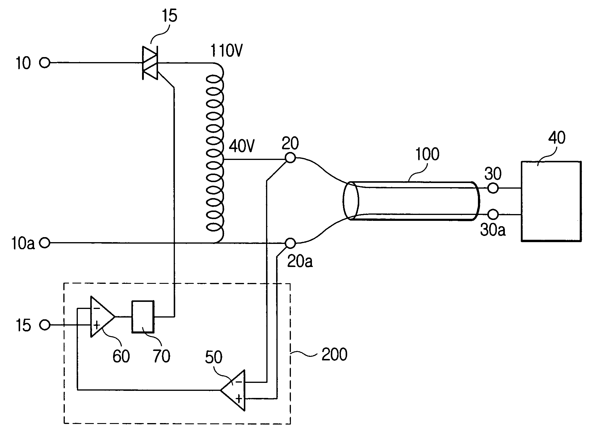
[0031] Reference will now be made in detail to the preferred embodiments of the present invention, examples of which are illustrated in the accompanying drawings.

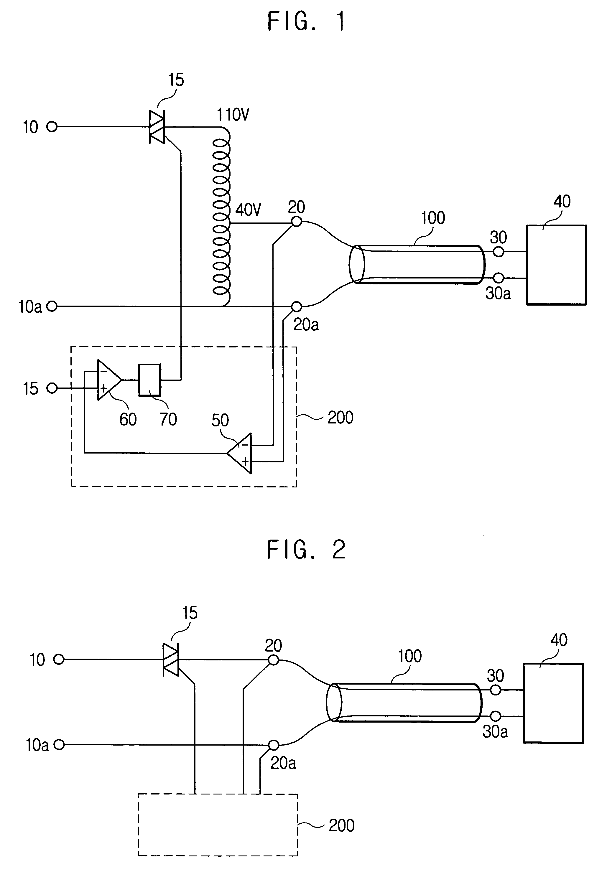
[0032]FIG. 2 is a power supply circuit of an electrofusion machine according to the present invention.

[0033] Unlike in FIG. 1, the electrofusion machine in FIG. 2 does not employ a transformer but employs a triac 115 so as to drop a commercial voltage to a voltage adapted for an application to a fitting.

[0034] According to the present invention, since the price of the triac fell considerably, an economical load is not large. Also, since the electrofusion machine of the present invention does not employ the transformer occupying 40% weight of a total weight, the mobility and the portability are enhanced.

[0035] Also, since the weight and the size of the machine are reduced, it is advantageous to deal with the machine on the spot.

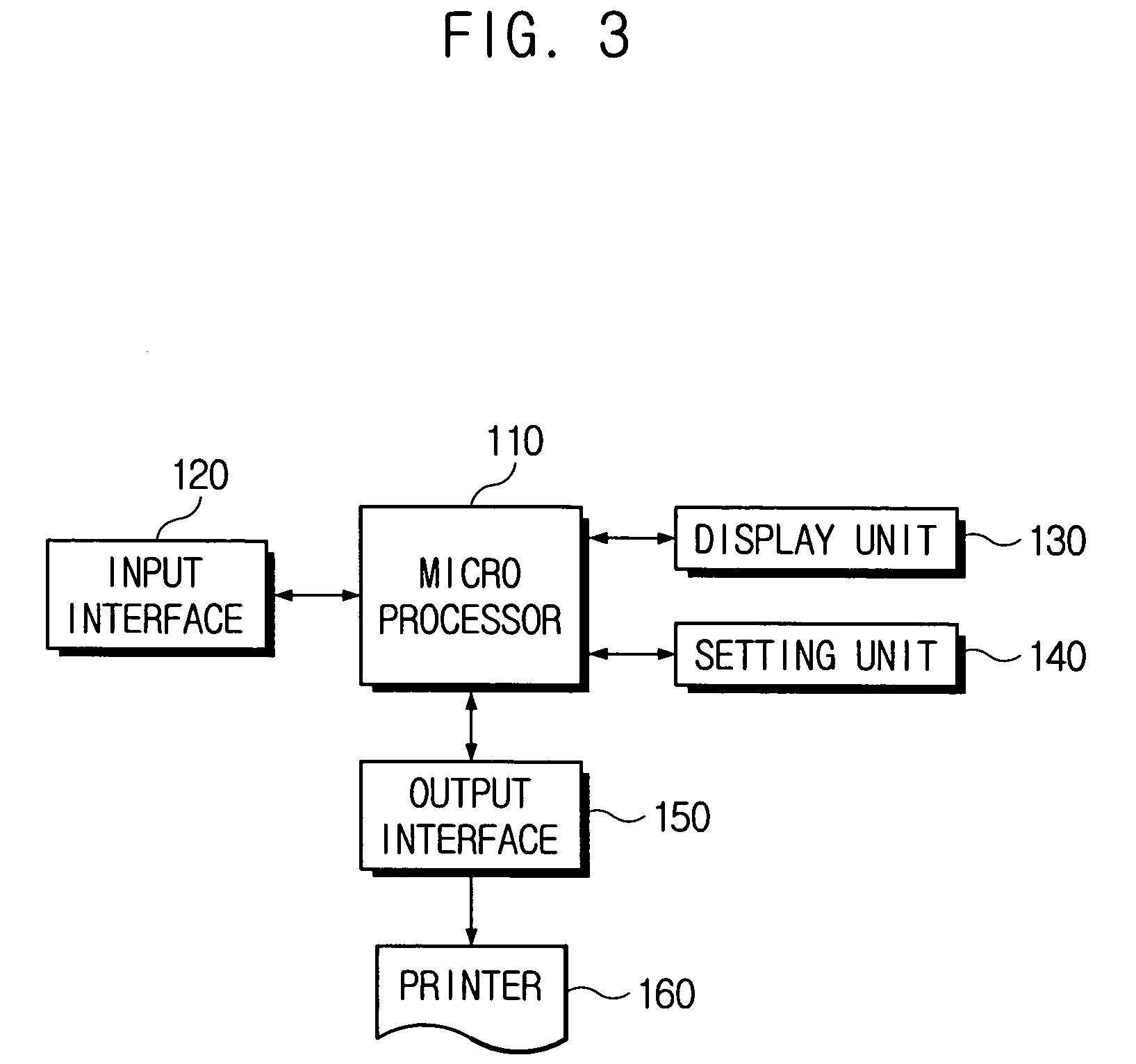
[0036]FIG. 3 is a block diagram showing a function construction of an electrofusion machine. ...


PUM

PropertyMeasurementUnit
Fractionaaaaaaaaaa
Sizeaaaaaaaaaa
Electric potential / voltageaaaaaaaaaa

Abstract

Provided is an improved electrofusion machine comprising: a power supply circuit having a triac configured to have a proper regulation for dropping a commercial voltage to a voltage adapted for a fitting; and a printer unit integrated with the electrofusion unit, for printing information regarding a work result of the fitting. According to the above construction, since the electrofusion machine does not use a transformer occupying 40% of a total weight of the machine, the mobility and portability are enhanced. Also, since the size of the machine is reduced, it is advantageous to deal with the machine on the spot.

Description

FIELD OF THE INVENTION [0001] The present invention relates to an electrofusion machine having an improved performance, and more particularly, to an electrofusion machine having reduced weight to enhance the mobility and portability, and capable of reporting a work result on the spot. DESCRIPTION OF RELATED ART [0002] An electrofusion machine was developed for bonding or branching a gas pipe or a water supply and drainage pipe having polyethylene- or ethylene-based copolymer as a main raw material. [0003] To bond two polyethylene pipes using the electrofusion machine, a polyethylene bonding material having a heating wire or heating element therein is placed on a bondage surface between the polyethylene pipes and a fitting, each of the two polyethylene pipes is inserted into both ends of the fitting, and current is supplied to the heating wire or heating element, so that heat is generated from the heating wire or heating element and thus inner surfaces of the fitting and outer circum...

Claims


Application Information

Patent Timeline
IPC IPC(8): H05B1/02
CPCB29C65/342B29C66/8618B29C66/90B29C66/96B29C66/967B29C66/9674B29C65/00B29C65/3476B29C66/9121B29C66/91313B29C66/91315B29C66/91411B29C66/91653B29C66/9672
Inventor DEASON, MIKE T.LEE, NAM-HOON
Owner DEASON MIKE T
Why Eureka
Try Eureka