Dispenser assembly

a technology for dispensing assembly and liquid, which is applied in the direction of liquid transferring devices, single-unit apparatuses, instruments, etc., can solve the problem of relatively slow process of dispensing the pump with the container, and achieve the effect of reducing working space and facilitating the assembly of the pump cap

Active Publication Date: 2006-04-27
AUTO KAPS
View PDF14 Cites 27 Cited by
  • Summary
  • Abstract
  • Description
  • Claims
  • Application Information

AI Technical Summary

Benefits of technology

[0012] The construction according to the invention in which the passage member or tube is not initially connected to the pump cap allows for easier assembly of the pump cap to the container due to the reduced working space required.

Problems solved by technology

A problem with the prior art assemblies is that the pick-up tube is carried by the pump and the tube is of a length that it reaches the bottom of the container.
This makes assembling the pump with the container a relatively slow process.
The problem with this type of construction is that it allows the pump cap to only be mounted in a single orientation relative to the container.

Method used


Image

  • Dispenser assembly
  • Dispenser assembly
  • Dispenser assembly

Examples


Embodiment Construction

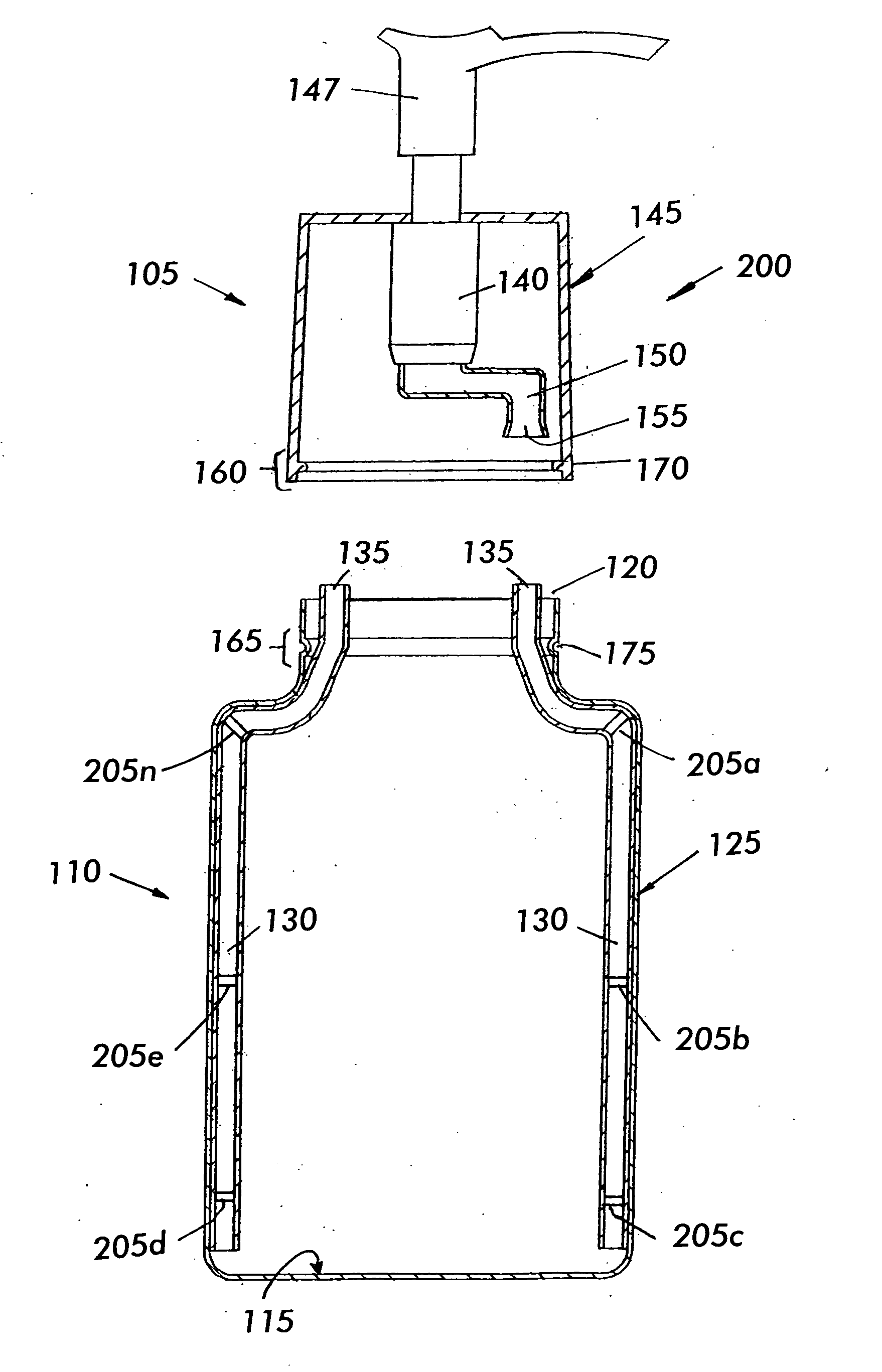
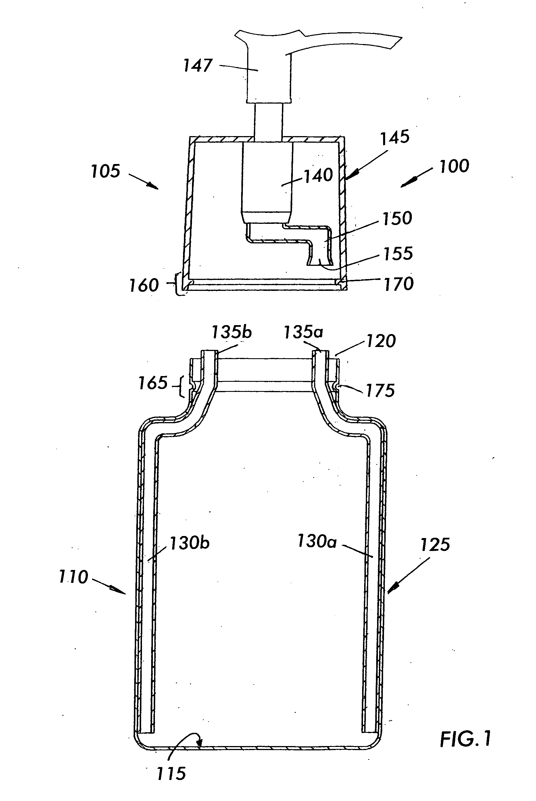
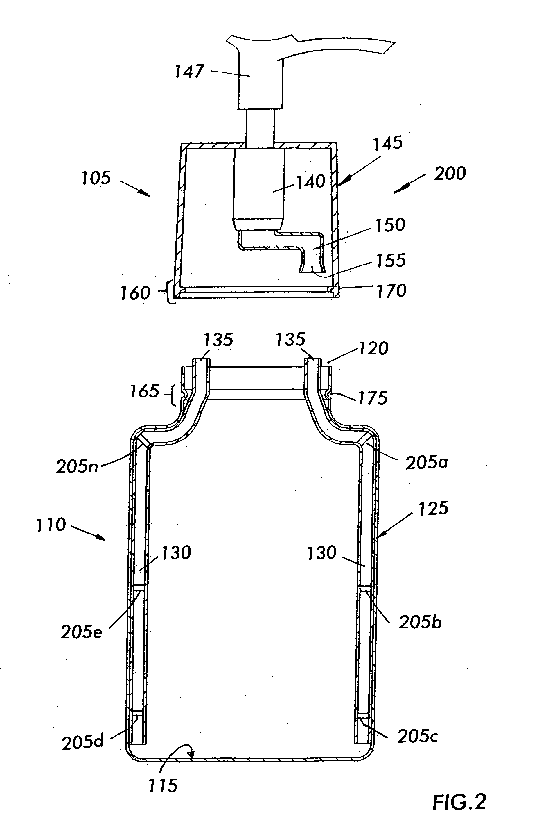
[0020] Referring to FIG. 1, there is seen a cross-sectional view of a first exemplary dispenser assembly 100 according to the present invention. Dispenser assembly 100 includes a pump cap 105 and a container 110 configured to sealingly engage with the pump cap according to the present invention to dispense a liquid enclosed within container 110.

[0021] Container 110 includes a bottom 115, an open top 120, and a side wall 125 disposed between and formed integrally with open top 120 and bottom 115. It should be appreciated that side wall 110 need not be formed integrally with open top 120 and bottom 115, but rather may be formed of a separate piece that is coupled, attached, or otherwise bonded to open top 120 and bottom 115. It should also be appreciated that container 110 may have any desired shape, such as square, oval, round, triangular, etc.

[0022] At least one passageway 130 is mounted to the inner surface of side wall 125 and extends from open top 120 to a position proximate bo...


PUM


Abstract

A dispenser assembly is provided. The dispenser assembly includes a container having a bottom, an open top and a side wall extending between the bottom and the open top, and a mating arrangement, the side wall having an inner surface; at least one container passageway mounted on the inner surface of the side wall and extending from the open top of the container to a position proximate to the bottom of the container; and a pump cap having a cap body, a pump mechanism arranged within the cap body, a pump cap passageway coupled to the pump mechanism, and a coupling arrangement arranged on the pump cap body and configured to detachably couple to the mating arrangement of the container such that the container passageway aligns with and sealingly engages the pump cap passageway in a fluid connection when the pump cap is mounted to the container. In this manner, the dispenser permits a fluid arranged within the container to flow through the container passageway and the pump cap passageway when the pump mechanism of the pump cap is activated.

Description

FIELD OF THE INVENTION [0001] The present invention relates to a liquid and a semi-liquid product dispensing assembly with a pump cap and a bottle on which the cap is mounted. BACKGROUND OF THE INVENTION [0002] Container and pump assemblies for products such as liquid soaps which are pumped, as well as products which are sprayed, such as household cleaners, hair spray and perfumes, etc. are known. Such conventional assemblies include a container having a neck and a pump connected to the neck. The pump has an elongated pick-up tube that extends down into the container for pulling up the liquid product stored within the container when the pump is operated. A problem with the prior art assemblies is that the pick-up tube is carried by the pump and the tube is of a length that it reaches the bottom of the container. As a result, when the pump is mounted on the container it must first be placed in an elevated position with the lower end of the pick-up tube above the entrance to the conta...

Claims


Application Information

Patent Timeline
Patent Type & Authority Applications(United States)
IPC IPC(8): G01F11/36B67D7/58B67D7/78
CPCB05B11/0037B05B15/005B05B15/066G01F11/028B05B15/08B05B15/652B05B15/30B05B15/68
Inventor HERZOG, KENNETH J.
Owner AUTO KAPS
Why Eureka
Try Eureka