
Direct reading stadia rod for use with laser level

a technology of laser level and stadia rod, which is applied in the field of land surveying, can solve the problems of high complexity of the mechanism of the stadia rod, cumbersome use, and inability to provide a direct read-out of the elevation, and achieve the effect of low cost, efficient measurement, and not complex in structur

Inactive Publication Date: 2006-04-27
BURKHART JR MAX E
View PDF14 Cites 14 Cited by
  • Summary
  • Abstract
  • Description
  • Claims
  • Application Information

AI Technical Summary

Benefits of technology

[0012] It is another object of the present invention to provide a direct-reading stadia rod for use with a laser level that is easy and inexpensive to use, the stadia rod having a compact sensing head and a retractable tape that can be clipped onto a workman's belt and easily carried.
[0014] It is yet another object of the invention to provide an elevation measuring device that is not complex in structure and which can be manufactured at low cost but yet, when properly calibrated at a benchmark elevation, efficiently measures and directly outputs geographic elevation data.

Problems solved by technology

This grade rod mechanism is highly complex and cumbersome to use.
This system is also quite complex and does not provide a direct read-out of the elevation.
The Zellner patent also requires laser transmission from a benchmark location of known elevation which limits the flexibility of the system.
This altitude information may then be displayed, stored or processed, but is limited to identifying only a given height on the rod, and does not provide a direct read-out of actual elevation.
All of these systems have limitations in terms of automatic elevation display, most of these devices being highly complex and commensurately expensive.

Method used


Image

  • Direct reading stadia rod for use with laser level
  • Direct reading stadia rod for use with laser level
  • Direct reading stadia rod for use with laser level

Examples


Embodiment Construction

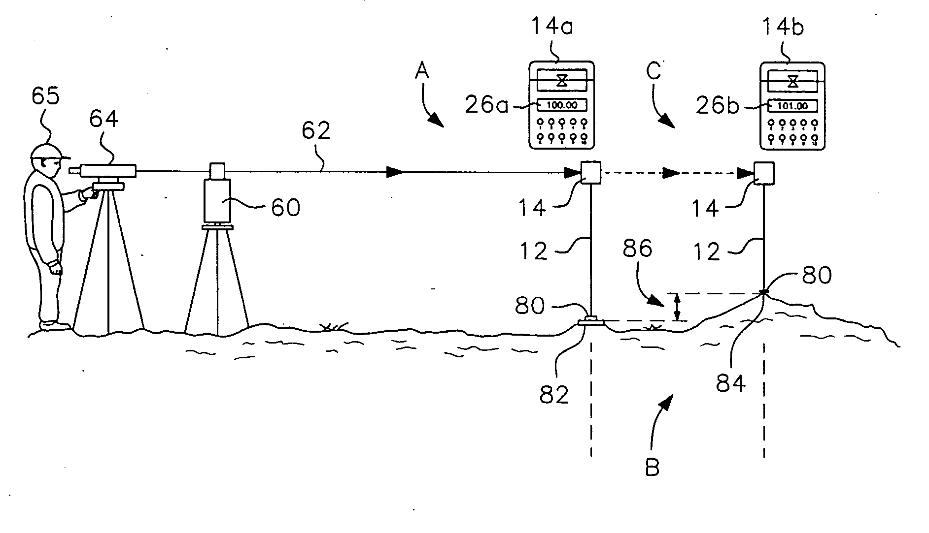
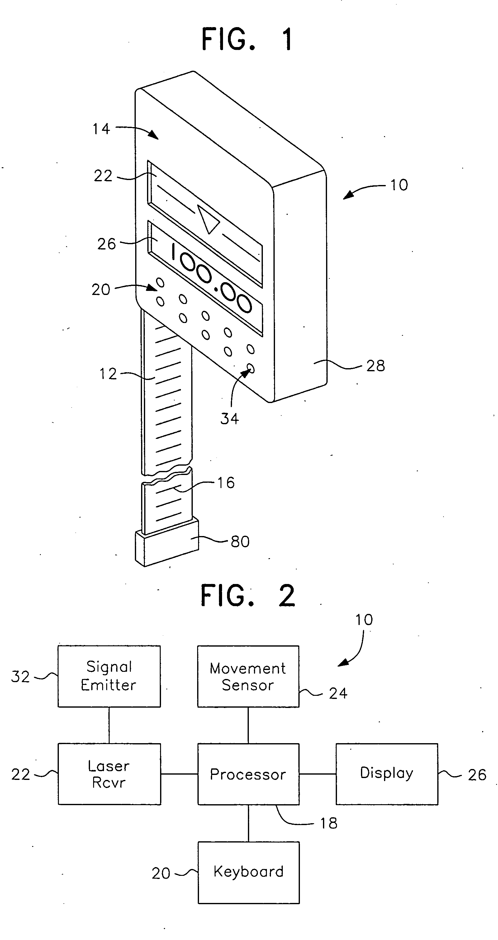
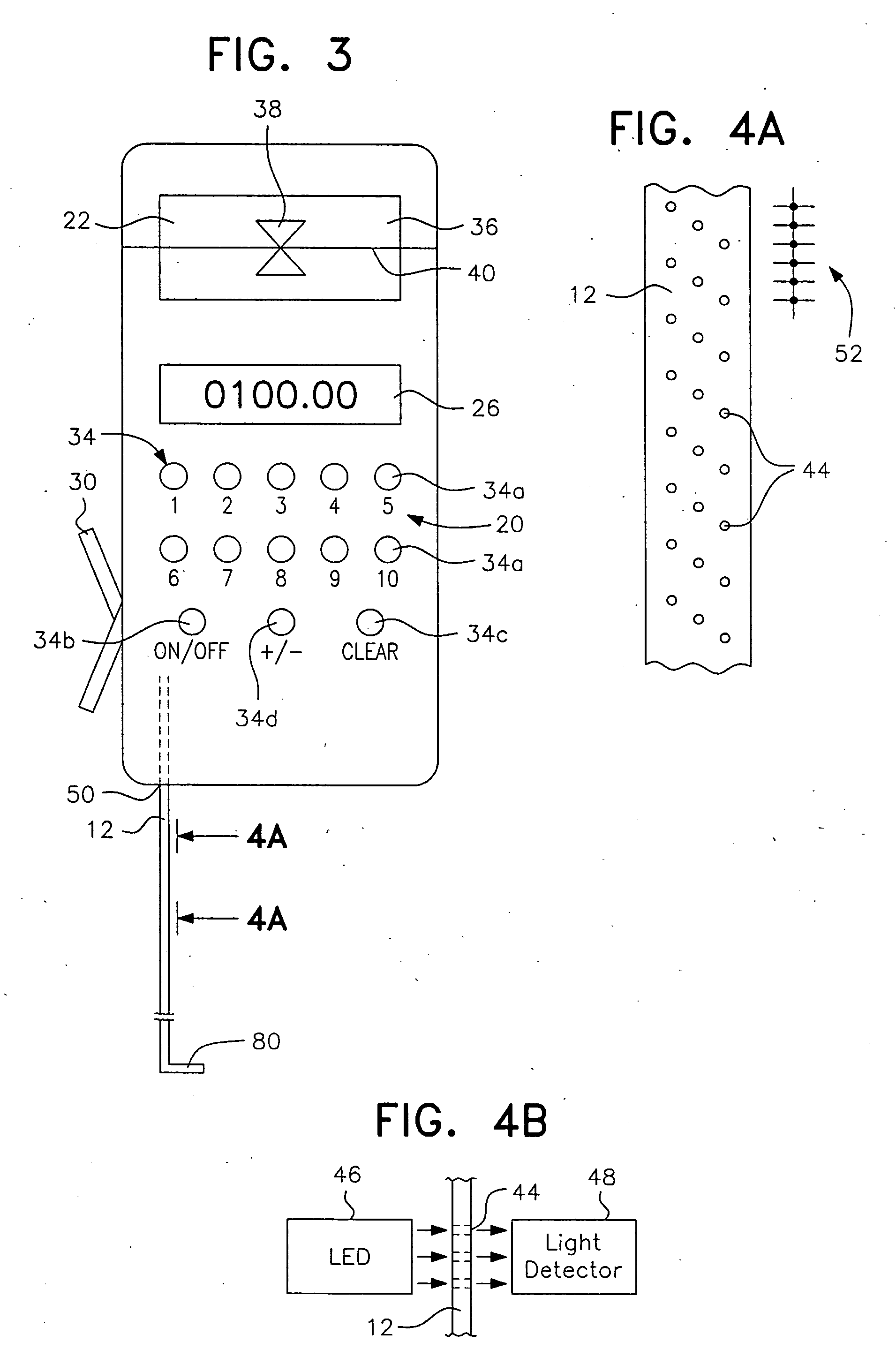
[0034] In describing a preferred embodiment of the invention illustrated in the drawings, specific terminology will be resorted to for the sake of clarity. However, the invention is not intended to be limited to the specific terms so selected, and it is to be understood that each specific term includes all technical equivalents which operate in a similar manner to accomplish a similar purpose.

[0035] As used herein in connection with the present invention, the term “stadia rod” is used to refer to a device that operates like a surveyor's rod but which may not actually include a “rod” as that term is generally understood. Instead, the “rod” may be a flexible tape or other measuring structure that may be retracted and extended, as well as a fixed length, relatively inflexible structure such as a pole.

[0036] Referring to the illustration provided in FIG. 1, the stadia rod according to the present invention, generally designated by the reference numeral 10, includes a rod or tape 12 an...


PUM


Abstract

A direct-reading stadia rod for use with a laser level includes a flexible tape and a sensing head that is movable therealong. The sensing head includes a keyboard, a movement sensor, a laser beam receiver, and a display. The rod is calibrated with a benchmark elevation by placing the base of the tape on a point of known elevation and moving the sensing head along the tape until it is properly aligned with the beam of a remotely located laser level. With the sensing head fixed at that location on the tape, the benchmark elevation is input using the keyboard. Thereafter, the tape is placed upon a second point of unknown elevation, and the sensing head is incrementally moved until the laser beam receiver again detects alignment with the laser plane. Based on data from the movement sensor indicating the distance moved by the sensing head from the benchmark position, the elevation of the second point is automatically determined and the output displayed.

Description

BACKGROUND OF THE INVENTION [0001] 1. Field of the Invention [0002] The present invention is related to the field of land surveying and more particularly to a stadia rod having an automatic elevation read-out display capability and a method for using the stadia rod. [0003] 2. Description of the Related Art [0004] Stadia rods are used by surveyors in conjunction with an optical level or a laser level to determine the differences in vertical elevation from a point of known elevation and to that of another point or points. [0005] The method used for centuries has been to view a stadia rod through an optical level. Markings provided on the stadia rod show exact graduations in a given scale, such as meters or feet, starting at the bottom and increasing incrementally up the rod. For example, if the rod is 8 feet in length, the top of the rod is marked 8′0″. Most commonly, surveyor's rods in the U.S. are marked in feet, as well as in tenths and hundredths of a foot. The height on the rod d...

Claims


Application Information

Patent Timeline
Patent Type & Authority Applications(United States)
IPC IPC(8): G01C3/08
CPCG01C3/08G01C15/006
Inventor BURKHART, MAX E. JR.
Owner BURKHART JR MAX E
Learn More