Disk drive device and installation mechanism for disk drive device

a technology of installation mechanism and disk drive, which is applied in the direction of casing/cabinet/drawer details, instruments, casings/cabinets/drawers, etc., can solve the problems of disk drive being disengaged from the system unit, screwing in the system unit, and burdening the worker, so as to reduce installation costs, and increase the installation workability

Inactive Publication Date: 2006-04-27
CITIZEN WATCH CO LTD
View PDF4 Cites 10 Cited by
  • Summary
  • Abstract
  • Description
  • Claims
  • Application Information

AI Technical Summary

Benefits of technology

[0034] The configuration, in which the protrusions are formed on the bottom cover, allows the protrusions to be created easily. In addition, because the bottom cover can be replaced easily, the protrusions can also be replaced easily.
[0039] As is apparent from the above description, the present invention increases the installation workability when a disk drive is installed and fixed in a system unit. The present invention also increases the installability of the disk drive in the system unit. The installation costs can be reduced. DISCLOSURE OF THE INVENTIONBrief Description of the Drawings

Problems solved by technology

Therefore, the installation work involving screwing in the system unit, where installation environment is restricted, is a burden to the worker and takes long.
Loose screwing becomes a factor that contributes to the incomplete fixing of the disk drive in the system unit and incomplete fixing, in turn, becomes a factor that causes the disk drive to be disengaged from the system unit.
When screws apply stress to the housing, there is a danger that the housing is deformed or warped by this stress.
Therefore, a deformation or warp in the housing may become a factor of misalignment in the head.
The screws also become a factor of higher costs.

Method used


Image

  • Disk drive device and installation mechanism for disk drive device
  • Disk drive device and installation mechanism for disk drive device
  • Disk drive device and installation mechanism for disk drive device

Examples


Embodiment Construction

[0060] A disk drive and a disk drive installation mechanism in the best mode for carrying out the present invention will be described below with reference to the drawings.

[0061] The following describes in detail a disk drive and a disk drive installation mechanism according to the present invention with reference to the drawings.

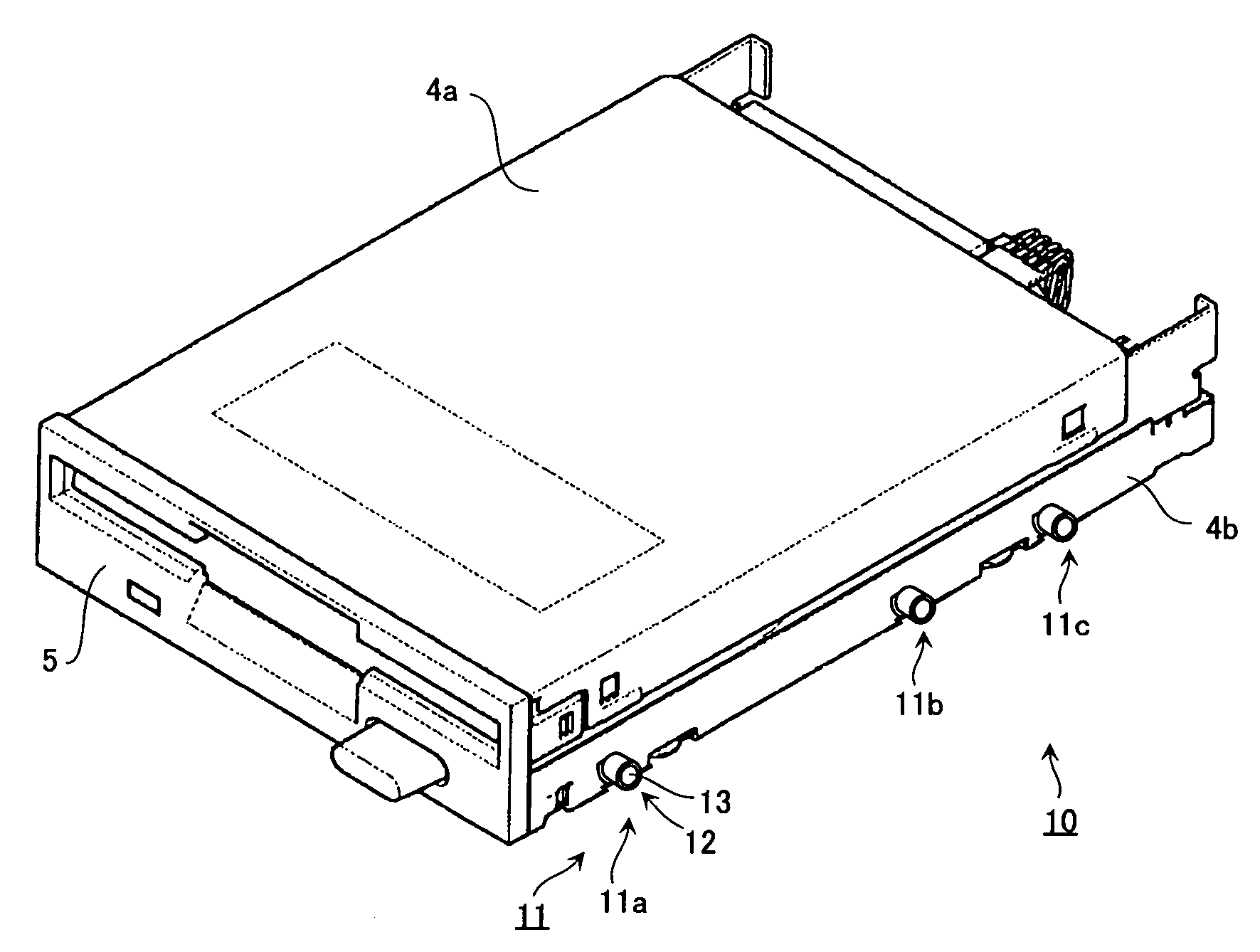
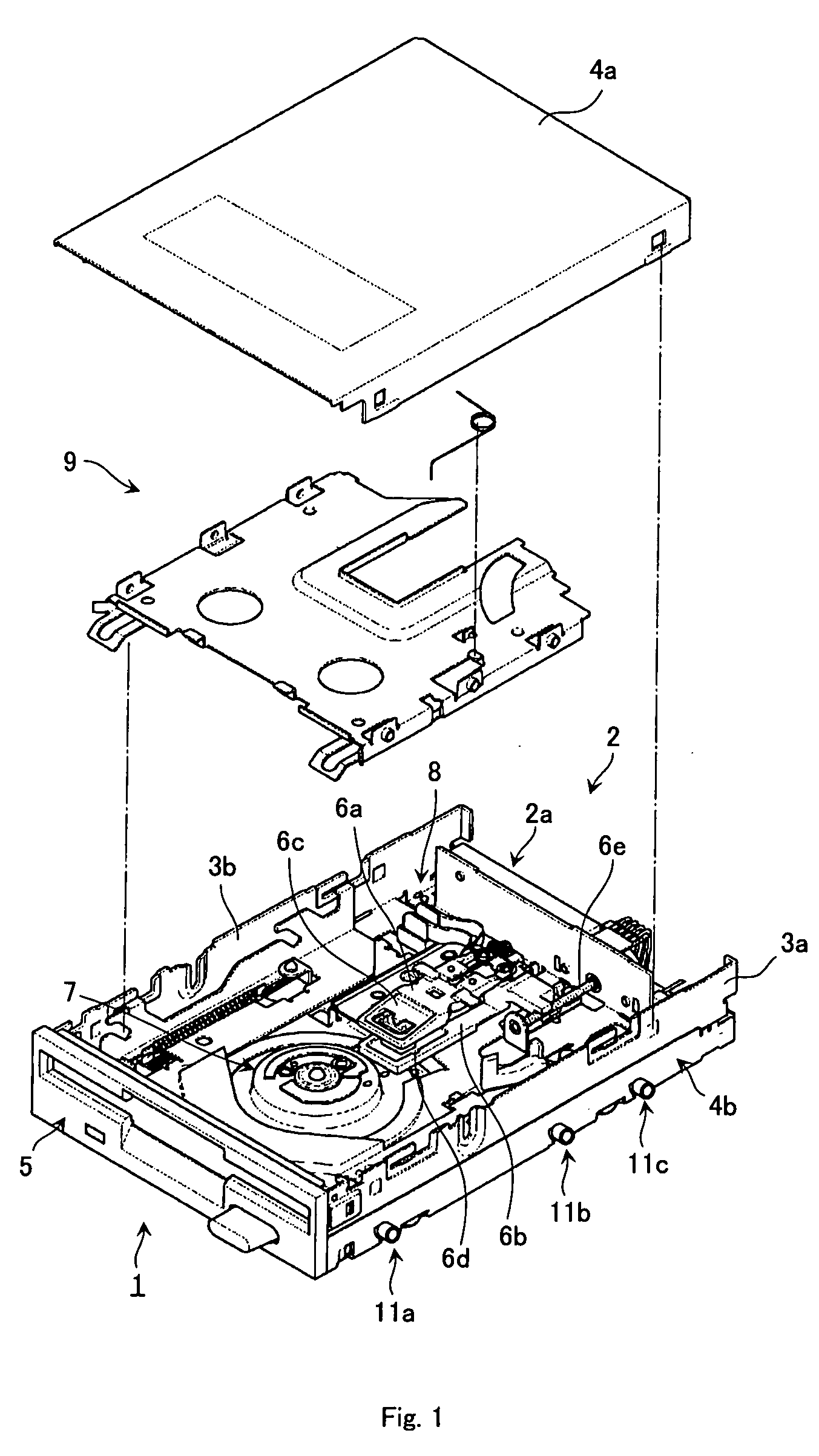
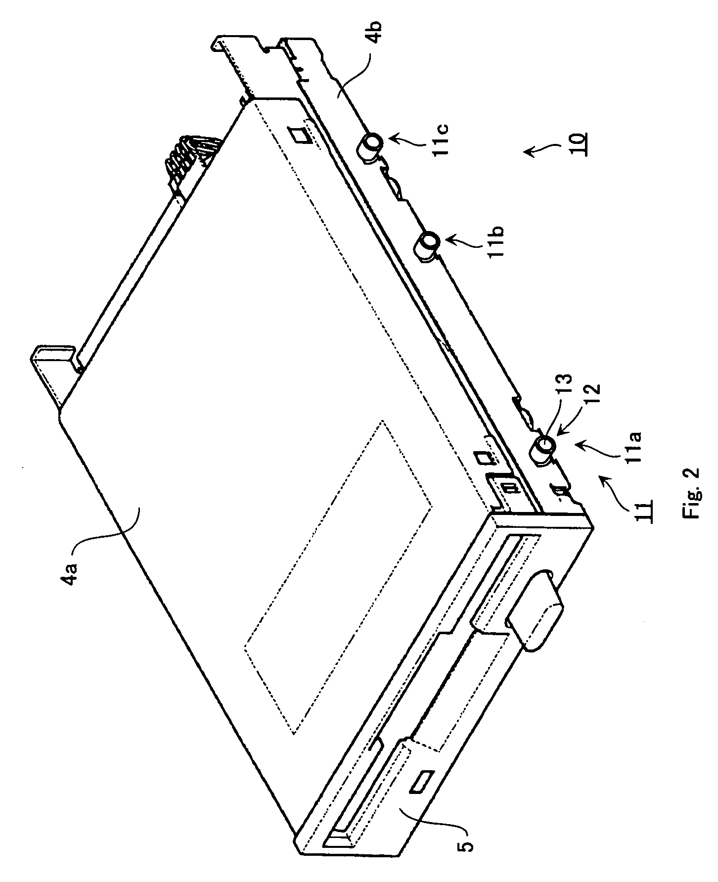
[0062] In an embodiment shown below, a combination of protrusions and long grooves will be described as an installation mechanism for installing a disk drive in a system unit. The protrusions and the long grooves are provided, one on the disk drive and the other on the system unit, and are fit together to install and fix the disk drive in the system unit. Which of the protrusions and the long grooves are provided on which of the disk drive and the system unit is arbitrary.

[0063] The following describes an embodiment in which the protrusions are provided on the disk drive and the long grooves are provided on the system unit with reference to FIG. 1 to FIG....


PUM

PropertyMeasurementUnit
diameteraaaaaaaaaa
thicknessaaaaaaaaaa
cylindrical shapeaaaaaaaaaa

Abstract

Instead of installation using screws, an installation mechanism is configured by an installation structure formed on a disk drive side and a mating installation structure formed on a system unit side and, using this mechanism, the disk drive is installed and fixed in the system unit. The installation structure on the disk drive has a fitting member that fits the disk drive into the system unit side, and this fitting member fits the disk drive into the system unit side for installing and fixing it therein without using screws. This increases workability and installability and reduces installation costs.

Description

TECHNICAL FIELD [0001] The present invention relates to the installation of a disk drive in a system unit. The present invention relates to a disk drive having a configuration for installation in a system unit, and to an installation mechanism for installing a disk drive in a system unit by allowing the disk drive and the system unit to work together. BACKGROUND ART [0002] The disk drive of a flexible disk device and so on is installed externally to, or internally in, the system unit such as a personal computer. An internal flexible disk device is installed by fixing it in the system unit by the manufacturer at manufacturing time or by fixing it in a free bay of the system unit by the user. In addition, at repair time or replacement time, it is sometimes required to remove the disk drive from the system unit or to install the disk drive in the system unit. [0003] As the installation structure of a disk drive in the system unit, screws are usually used as fixing means. Some of such i...

Claims


Application Information

Patent Timeline
Patent Type & Authority Applications(United States)
IPC IPC(8): G11B17/00G11B33/12
CPCG11B33/124
Inventor OHISHI, YOSHIYUKI
Owner CITIZEN WATCH CO LTD
Why Eureka
Try Eureka