Speaker device

a speaker device and mounting structure technology, applied in the direction of transducer diaphragms, transducer details, electrical transducers, etc., can solve the problems of reducing the sensitivity of the speaker device, the cap becomes heavy by the amount of increased thickness of the cap, and the abnormal sound (flutter) of the cap is problematic. to prevent the occurrence of abnormal sound

Inactive Publication Date: 2006-04-27
PIONEER CORP +1
View PDF8 Cites 8 Cited by
  • Summary
  • Abstract
  • Description
  • Claims
  • Application Information

AI Technical Summary

Benefits of technology

[0007] The present invention has been achieved in order to solve the above problems. It is an object of this invention to provide a speaker device, having a mounting structure of a cap and a diaphragm, capable of preventing occurrence of an abnormal sound (flutter) of the cap.

Problems solved by technology

Therefore, a vibrating area of the cap at the time of driving of the speaker device is large, and due to the vibration, an abnormal sound (flutter) problematically occurs from the cap.
As a method of avoiding such a problem, there is known a method of making the cap thicker so that the vibration of the cap hardly occurs, thereby preventing the occurrence of the abnormal sound (flutter) However, if such a method is employed, the cap becomes heavy by the amount of increased thickness of the cap, and sensitivity of the speaker device decreases as a new problem

Method used


Image

  • Speaker device
  • Speaker device
  • Speaker device

Examples


first embodiment

[0036] In a first embodiment, it is prevented that an abnormal sound (flutter) occurs from the cap at the time of the driving of the speaker device, by bonding the cap and the diaphragm at a predetermined position.

(Configuration of Speaker Device)

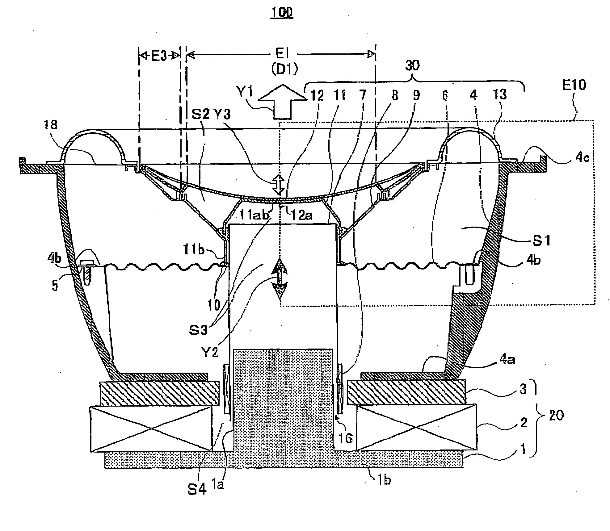
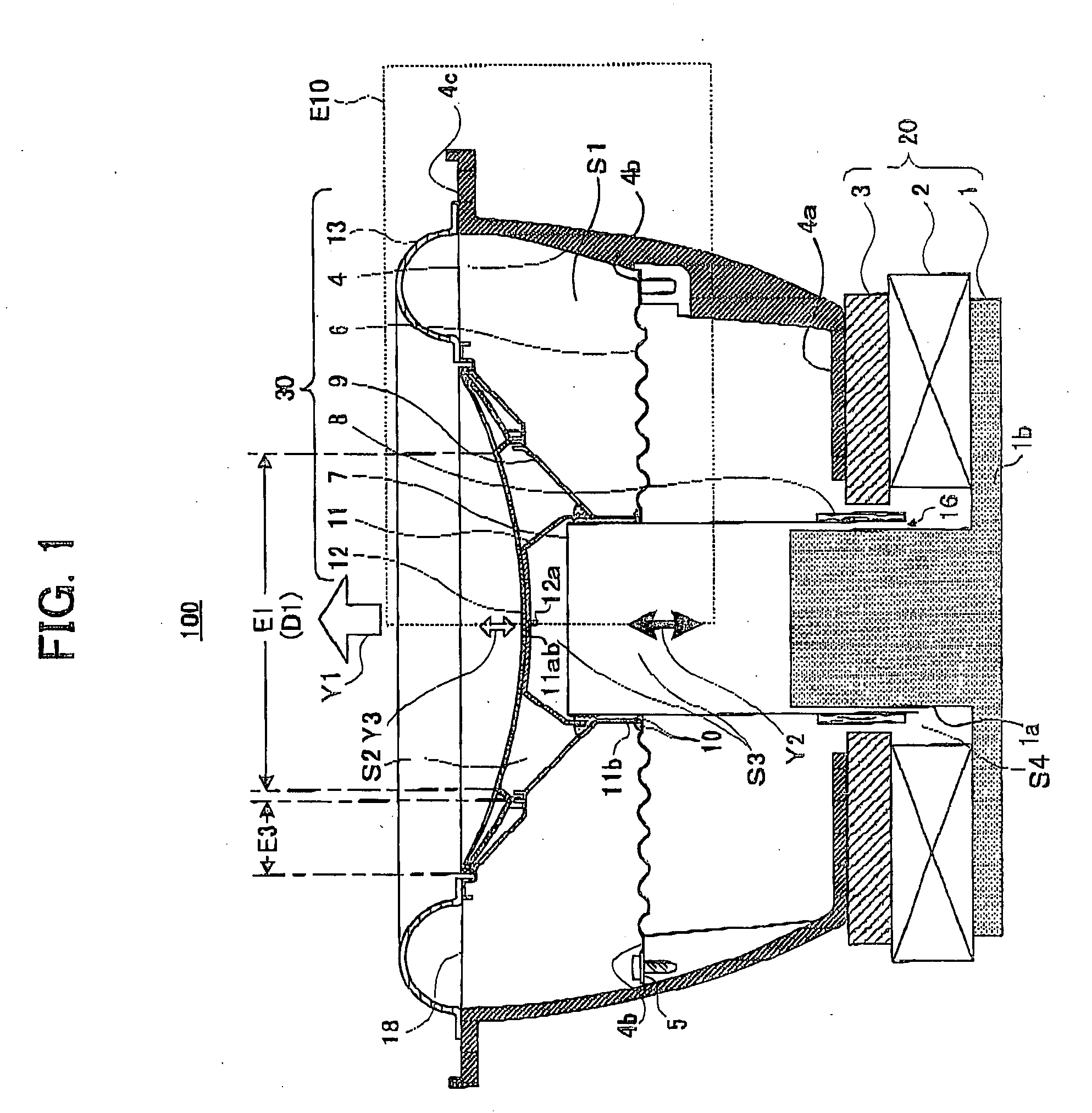
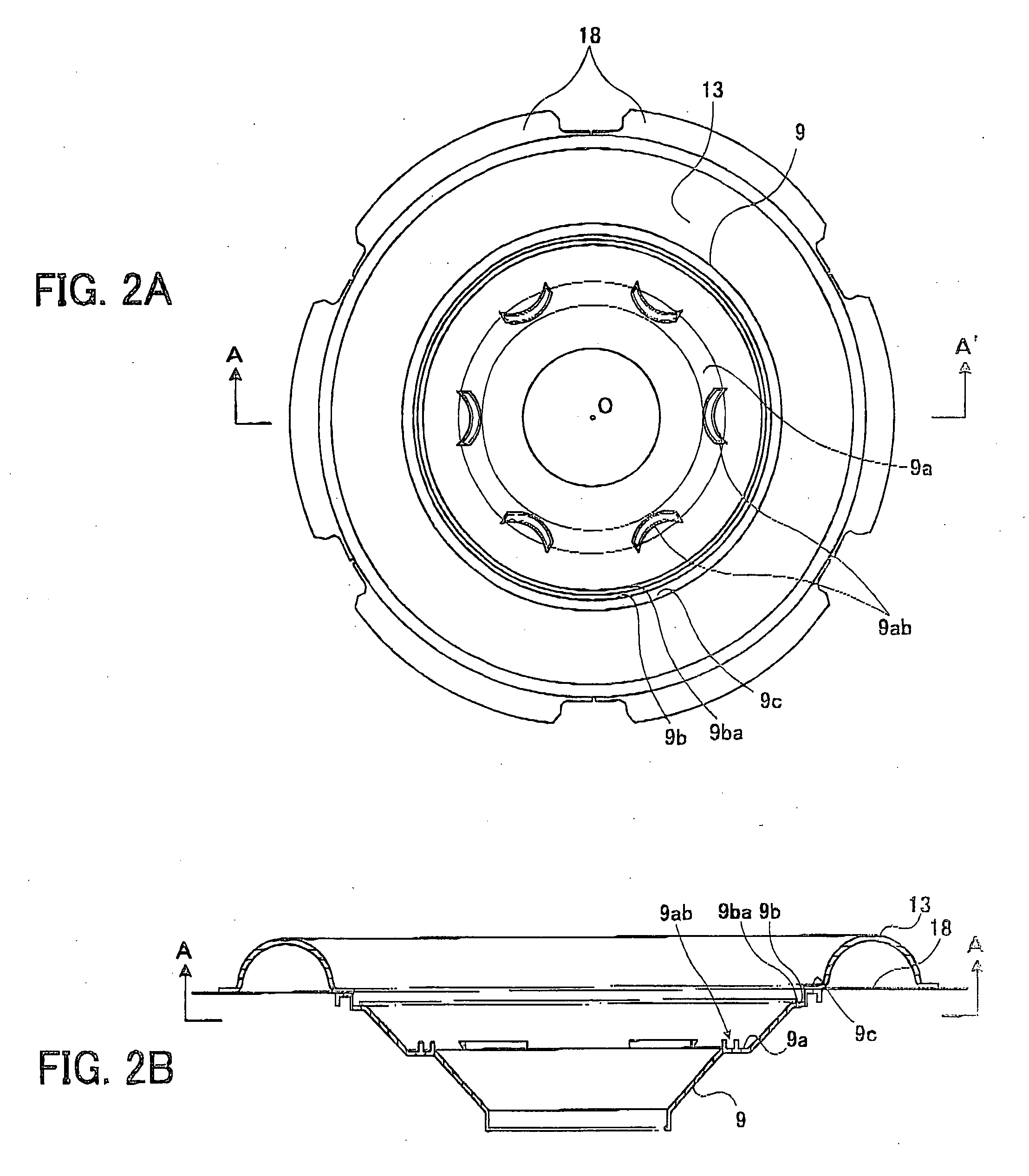
[0037]FIG. 1 schematically shows a configuration of a speaker device 100 according to the first embodiment of the present invention. The speaker device 100 of the first embodiment is the so-called subwoofer-type speaker device. Therefore, the speaker device 100 of this embodiment can be preferably used as an on-vehicle speaker. FIG. 1 shows a cross-sectional view when cutting the speaker device 100 by a plane including a central axis thereof. The description will be given of the configuration of the speaker device 100 of the first embodiment with reference to FIG. 1 to FIGS. 4A and 4B, below.

[0038] As shown in FIG. 1, the speaker device 100 mainly includes a magnetic circuit system 20 having a yoke 1, a magnet 2 and a plate 3, a vibrati...

second embodiment

[0060] In a second embodiment, by providing the ventilation portion on the above-mentioned components of the speaker device 100, e.g., the supporting cap 11, the mechanical resistance at the time of the movement of the vibration system 30 is reduced. Thereby, the deterioration of the sound quality can be prevented.

[0061] First, the outline of the second embodiment will be explained with reference to FIG. 1.

[0062] In the speaker device 100 shown in FIG. 1, a space S1 among the diaphragm 9, the edge 13, the frame 4 and the damper 6 and a space S2 among the diaphragm 9, the cap 12 and the supporting cap 11 are closed, respectively In addition, a space S3 among the voice coil bobbin 7 formed into a substantially cylindrical shape, the supporting cap 11 and the pole portion 12 is connected to a space S4 among the magnet 2, the plate 3 and the yoke 1 via the magnetic gap 16.

[0063] In the speaker device 100 having such a configuration, when the voice coil bobbin 7 is assumed to move in ...


PUM


Abstract

A speaker device includes a vibration system, having a voice coil bobbin, a diaphragm, a supporting cap and a cap, and a magnetic circuit system. The inner peripheral edge portion of the diaphragm is mounted on an area in the vicinity of the upper end portion of the outer peripheral wall of the voice coil bobbin. The projecting portion of the cap is inserted into the opening of the supporting cap, and the supporting cap is placed under the cap. Each of the projecting portions of the cap is fixed to each of the correspondent recessed portions of the diaphragm, and the claw portion of the cap is fixed to the projecting portion of the diaphragm and the third flat portion.

Description

BACKGROUND OF THE INVENTION [0001] 1. Field of the Invention [0002] The present invention relates to a mounting structure of a cap and a diaphragm in a speaker device. [0003] 2. Description of Related Art [0004] Conventionally, there is known an external-magnet type speaker device including a vibration system having a voice coil bobbin, a diaphragm and a cap having a dustproof function, and a magnetic circuit system having a yokes a magnet and a plate. In such a speaker device, one portion (mounting surface), of an outer peripheral edge portion of the cap is mounted on an area in the vicinity of an outer peripheral edge portion of the diaphragm via an adhesive, and the cap is arranged at a position covering an upper surface of the voice coil bobbin, for example. [0005] There is known a speaker device in which the outer peripheral edge portion of the diaphragm having an upper-side diaphragm and a lower-side diaphragm is mounted onto an inner side edge (see U.S. Pat. No. 6,496,590 and...

Claims


Application Information

Patent Timeline
Patent Type & Authority Applications(United States)
IPC IPC(8): H04R1/00
CPCH04R7/122H04R9/02H04R9/04
Inventor KAIYA, TERUAKISATO, SEIYA
Owner PIONEER CORP
Why Eureka
Try Eureka